
 E-mail Alert
 RSS
RSS
-
摘要
为了解决装车机器人装车前货车车体位置和尺寸测量的问题,搭建了基于二维激光雷达的车体智能测量系统,并重点研究了该系统的标定方法。通过旋转平台带动二维激光雷达,利用单个二维激光雷达获得被测车体的三维信息。针对现有激光雷达测量系统标定方法复杂、标定件制作困难等问题,以321坐标系建立法为基础,提出了一种基于三平面标定板的系统参数标定方法,建立了标定数学模型,并详细给出了该标定方法的原理及步骤。在实验室搭建测量系统进行了标定实验以及模拟车体测量实验,在户外对真实车体进行了测量实验。实验结果表明,本测量系统的最大车体尺寸长度测量误差为26.4 mm,最大角度测量误差为0.18°,完全满足装车精度要求。
Abstract
To carry out the measurement of vehicle body position and dimension of loading robot before loading, an intelligent vehicle body measurement system based on two-dimensional LiDAR was provided, and the calibration method of this system was studied as a key point. The two-dimension LiDAR was driven by rotating the platform, and the three-dimensional information of car body measured was obtained by using the single two-dimensional laser radar. In allusion to the complexity of calibration method of LiDAR measurement system and the difficulty in making calibration pieces, a system parameter calibration method was proposed based on 321 coordinate system building method, and mathematical models of calibration was established, with the principle and procedure of calibration method in detail. Measurement system was set up in a laboratory to carry out calibration experiment and measurement experiment on simulation vehicle body, and the measurement experiment for real vehicle body was conducted outside. The experiment result shows that the maximum measurement error of vehicle body size and length of this measurement system was 26.4 mm; maximum angle measurement error was 0.18 degree, which fully meets the precision requirements of loading.
-
Key words:
- vehicle body position measurement /
- LiDAR /
- loading robot /
- calibration
-
Overview
Overview: At present, the material loading in China is basically in semi-automatic phase. The loading work is mainly completed by manpower and trolley, fork lift truck and telescopic belt conveyor, which is with low loading efficiency, large labor intensity. The industry crying needs intelligent loading robot to achieve the intelligent loading of the materials, while the vehicle shape and bucket size of the vehicle to be loaded should be firstly determined to achieve intelligent loading. Therefore, this paper established an intelligent vehicle body measurement system based on two-dimensional LiDAR, a system parameter calibration method was proposed based on 321 coordinate system building method, and mathematical models of calibration was established, giving the principle and procedure of calibration method in detail. The result shows that the maximum measurement error of vehicle body size and length of this measurement system was 26.4 mm; maximum angle measurement error was 0.18°, which fully meets the precision requirements of loading.
The specific calibration steps are: 1) establish LiDAR coordinate system, rotation center coordinate system, and robot loading coordinate system. The origin of LiDAR coordinate system o0 is located at the optical center of LiDAR.y0o0z0 plane is the scanning plane of LiDAR, axis o0y0 corresponds to the 45° line scan direction of LiDAR, axis o0x0 points in the dead ahead of LiDAR in front. The intersection o1 of rotation axis l of rotating platform and plane x0o0y0 is the origin of rotation center coordinate system. Three coordinate axes of rotation center coordinate system are parallel to the three axes of radar coordinate system. Loading coordinate system o2-x2y2z2 is located in the right front of the vehicle under test; 2) obtain the conversion relation between LiDAR coordinate system and rotation center coordinate system according to the installation location relationship of LiDAR and rotating platform; 3) assume that the coordinate-transformation matrix of rotation center coordinate system and loading coordinate system is T. Then calculate matrix T by substituting in special point coordinates from which we could transfer the calibration problem to looking for special point; 4) suspend a calibration board (about 2 m×2 m) over the axis o2x2 and axis o2y2 of loading coordinate system to ensure that the calibration plate is suspended directly above the axis; 5) scan the calibration plane and its adjacent ground, and two calibration plates and flat area are used as three calibration planes, then fit three plane equations, establish the coordinate system by means of 321 method and obtain the coordinates of four special points, and then solve the Tmatrix. Finally, the calibration of vehicle body measurement system is completed.
-
1. 引言
目前,国内的物料装车基本上是处于半自动化阶段[1]。主要通过人工加推车、叉车、伸缩式皮带输送机、码垛机器人等辅助工具来完成装车作业,不仅装车效率低、工人劳动强度大,而且诸如水泥化肥等物料会对装车工人的身体健康造成严重的危害[2-3]。因此,迫切需要智能化的装车机器人,实现智能装车首先需要确定待装车辆车体位姿和车斗尺寸,所以车体位姿测量及其标定方法是其核心关键技术之一。
通常大尺度三维测量技术可分为基于视觉和基于激光测距原理的两类[4-5]。视觉系统对于环境的要求较高,不适用于高粉尘的环境,在室外条件下受恶劣天气、光照等影响较大,因此不适用于车体测量。基于测距原理的激光雷达由于具有测量速度快、精度高、抗干扰能力强等优点,在各个领域得到广泛的应用。尤其是在新兴的机器人视觉领域内,很多学者和研究人员对激光雷达的应用及其标定方法进行了广泛的研究[6-9]。浙江大学的项志宇等人[10]提出用摆动装置带动二维激光雷达实现俯仰-45°~45°范围内的三维扫描,并通过扫描雷达正前方一定距离处垂直于地面的靶标,从获取的距离值和参数的关系反求出所有标定参数。该方法扫描范围小,且在标定过程中忽略了雷达横滚角,从而降低了该方法的标定精度。中南大学的彭梦等人[11]提出将激光雷达安装在车载平台上对双平行平面标定板进行扫描,然后利用标定板上的扫描信息以及标定板的特殊结构计算出激光雷达相对于车体的俯仰角度和偏转角度。但在该方法中激光雷达的安装位置采用手工测量,不仅测量精度低,而且忽略了激光雷达的安装误差。上海交通大学的石路[12]采用中空的四棱锥作为标定靶,研究了一种基于平面几何射影变换原理的标定方法,但该方法操作繁琐、算法复杂且标定靶难以制作。
针对以上方法存在的不足,结合车体测量的特点设计了一种旋转二维激光雷达测量系统,通过对激光雷达和旋转平台的同步控制,实现了对车体的空间三维测量,并针对本测量系统提出了一种简单实用的基于三平面标定板的标定方法。
2. 系统组成
2.1 智能装车机器人整体系统
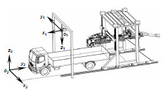
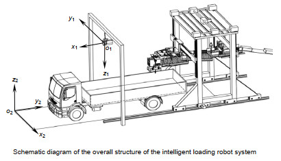
智能装车机器人整体系统的组成示意图如图 1所示,其主要由①车体测量子系统、机器人移动子系统(包括前后⑦行走机构、③竖直升降机构和④横向移动机构)、⑧柔性传送链和⑨装车机械手组成。当运输车辆停在⑩装车区域时,车体位姿测量系统自动获取运输车辆的车体位置和车斗尺寸信息;然后系统自动生成⑤包装物料在车斗内的码垛方案;最后由控制系统控制机械手将袋装物料码放到车斗的指定位置。
2.2 车体测量系统
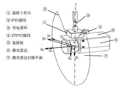
车体测量系统主要完成车体位置和车斗尺寸的自动测量,其组成示意图如图 2所示,主要由导电滑环、旋转工作台、二维激光雷达、连接板等部件组成。本文所选用的激光雷达扫描范围是270°,角分辨率为0.25°,即在扫描平面上从光心点o0发出1081条射线,射线遇到障碍物后返回激光雷达,根据光学原理求得障碍物到光心的距离。该激光雷达的扫描频率为50 Hz,即每秒完成50次截面扫描。二维激光雷达通过连接板与旋转工作台相连,l为旋转工作台的旋转轴。测量系统工作时,旋转工作台带动二维激光雷达绕l轴进行转动从而实现对车体的三维扫描,其中旋转平台的旋转速度可调,单次车体扫描最快可在15 s内完成,后文中所有扫描数据的获取均在25 s以内。
对整个车体测量装置引入三个坐标系:激光雷达坐标系、旋转中心坐标系以及装车坐标系。激光雷达坐标系的原点o0位于激光雷达的光心点,y0o0z0平面为激光雷达的扫描平面,o0y0轴对应激光雷达的45°扫描线方向,o0z0轴对应激光雷达的135°扫描线方向。旋转轴l与x0o0y0平面交于o1点,以o1为原点建立旋转中心坐标系,旋转中心坐标系的三个坐标轴分别平行于雷达坐标系的三个轴。在测量过程中,旋转中心坐标系保持不变,而激光雷达坐标系的位置会随激光雷达的旋转而改变。如图 1所示,装车坐标系o2-x2y2z2位于地面停车区域的右前方,在装车过程中机器人移动子系统以装车坐标系为基础进行装车码放。点A为车斗内部左前方底角点,也是装车的起始点,点B为车斗内部左后方底角点。在此,定义直线AB在装车坐标系o2x2y2平面上的投影与o2y2轴的夹角为车辆停放倾斜角ω(当ω大于某阈值时需要对车辆停放位置进行调整)。测得A点的位置以及角ω的大小即可获取车体位置,测得车斗底部四个角点的位置以及车帮高度即可获取车斗的尺寸。
在装车前首先要对车体测量系统进行系统标定,将几个坐标系建立联系,进而将激光雷达测得的车体位置和车斗尺寸信息传递给机器人移动子系统,然后才能完成袋装物料的自动装车。
3. 系统标定
3.1 车体测量系统标定数学模型
在测量过程中,激光雷达坐标系的位置不断变化。若想获取被测对象的三维信息,应求得每一时刻激光雷达坐标系与旋转中心坐标系的转换关系[13]。当激光雷达旋转α角度后,激光雷达坐标系和旋转中心坐标系的位置关系如图 3所示。将激光雷达坐标系绕旋转中心坐标系的o1z1轴逆时针旋转α角度,然后沿o1x1轴的负方向平移距离r,即可与旋转中心坐标系重合(r为激光雷达的旋转半径,r=o0o1)。
因此,旋转中心坐标系与激光雷达坐标系的转换关系为
[x1y1z11]=[[cosα−sinα00sinαcosα0000100001][100r010000100001]][x0y0z01]。 (1) 由于激光雷达存在安装误差,所以平面o1x1y1与平面o2x2y2不平行,且o1x1轴与o2y2轴不平行。因此将旋转中心坐标系绕其自身o1x1轴顺时针旋转θx度(θx≈180°),再绕其o1z1轴逆时针旋转θz度(θz≈90°),最后绕其自身o1y1轴旋转θy(θy≈90°),即可与装车坐标系的三个轴互相平行。然后分别沿其自身三个坐标轴方向平移Δx、Δy、Δz距离即可与装车坐标系重合。装车坐标系与旋转中心坐标系的坐标变换矩阵为
T=[x1y1z11]=[10000cosθx−sinθx00sinθxcosθx00001] ⋅[cosθz−sinθz00sinθzcosθz0000100001] ⋅[cosθy0sinθy00100−sinθy0cosθy00001]⋅[100Δx010Δy001Δz0001]。 综上,车体测量子系统的标定数学模型为
[x2y2z21]=T[x1y1z11]=T[[cosα−sinα00sinαcosα0000100001]⋅[100r010000100001]]⋅[x0y0z01]。 (2) 由于旋转平台自带编码系统,所以α可通过旋转平台的反馈得知。查询sick激光雷达产品手册可知r=16.8 mm。因此,解得矩阵T即可求得车体测量子系统的数学模型。
3.2 标定参数求解
相对于装车坐标系来说,激光雷达的安装角度和安装位置难以精确测量,即Δx、Δy、Δz等标定参数难以获取。为了避免多个参数分别求取造成误差累积,本文采用直接求解矩阵T的方法来减小标定误差。结合矩阵相乘的特点,采取代入特殊解的方法求解矩阵T。设旋转中心坐标系和装车坐标系的转换关系如式(3)所示,将表 1中四组特殊解带入式(3)恰好能求解矩阵T的逆。
表 1. 四组特殊解Table 1. Four sets of special solutions特殊解 (x2, y2, z2) (x1, y1, z1) 第一组 (0, 0, 0) (x11, y11, z11) 第二组 (x21, 0, 0) (x12, y12, z12) 第三组 (0, y21, 0) (x13, y13, z13) 第四组 (0, 0, z21) (x14, y14, z14) | Show Table DownLoad:
CSV
DownLoad:
CSV
T−1[x2y2z21]=[a1a2a3a4a5a6a7a8a9a10a11a120001][x2y2z21]=[x1y1z11]。 (3) 3.3 标定方法
分析表 1中四组特殊解可得,第一组解就是装车坐标系的坐标原点(0, 0, 0)及该点在旋转中心坐标系上的坐标(x11, y11, z11),第二组解就是装车坐标系中o2x2轴上一点(x21, 0, 0)及该点在旋转中心坐标系上的坐标(x12, y12, z12),同理可得第三组和第四组解分别是装车坐标系中o2y2轴和o2z2轴上一点及其在旋转中心坐标系下的坐标。因此,找到这四个特殊点就可以解得矩阵T。
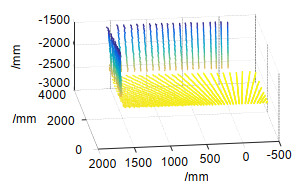
由于本文所选激光雷达的系统误差为±30 mm,统计误差为±12 mm,所以为了减小标定误差,本文通过扫描三平面标定板,统计大量点云数据拟合平面并结合321坐标系建立法来找到这四个特殊点。标定板摆放示意图如图 4所示。采用雷达扫描测量系统对标定板进行扫描,三平面标定板点云如图 5所示,分别拟合三个平面方程如下:
平面1:
−0.009x1+0.017y1+0.998z1−2696.908=0, (4) 平面2:
0.999x1+0.017y1+0.042z1−1875.577=0, (5) 平面3:
−0.017x1+0.999y1+0.028z1−1225.352=0。 (6) 根据三平面方程可知,三平面并不完全互相垂直。因此以平面1为装车坐标系中o2x2y2平面,平面1和平面2的交线为o2x2轴,三个平面的交点为o2点,采用321法在旋转中心坐标系中建立装车坐标系,然后在装车坐标系中找到四个特殊点,进而求解矩阵T。
具体求解步骤如下:
1) 联立式(4)~式(6),解得三平面交点o2(x11, y11, z11),即第一个特殊点,该点在装车坐标系下的坐标为(0, 0, 0);
2) 联立式(4)、式(5),解得直线o2x2在旋转中心坐标系下的直线方程。在该直线上任取一点,设该点为E(x12, y12, z12),求E点到o2点的距离即x21,即该点在装车坐标系中的坐标为(x21, 0, 0);
3) 此时已知装车坐标系的o2x2y2平面、坐标原点o2以及o2x2轴,以o2x2轴为法向量,过o2点建立y2o2z2平面。平面y2o2z2与平面x2o2y2交于o2y2轴,在该轴上任取一点F,F点在装车坐标系中的坐标为(0, y21, 0),在旋转中心坐标系中的坐标为(x13, y13, z13);
4) 以o2y2轴为法向量,过o2点建立平面x2o2z2。平面x2o2z2与平面x2o2y2交于o2z2轴,在o2z2轴上任取一点G,G点在装车坐标系中的坐标为(0, 0, z21),在旋转中心坐标系中的坐标为(x14, y14, z14);
5) 将o2、E、F以及G点在装车坐标系以及旋转中心坐标系中的坐标带入式(3)解得矩阵T-1,进而求解矩阵T,最终解得装车坐标系与雷达坐标系的转换关系。
4. 实验
4.1 标定实验
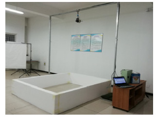
在实验室搭建测量系统如图 6。以地面作为标定板1,采用两块较为平整的硬布作为标定板2和标定板3,硬布下端通过两个吊坠自然下垂来控制标定板2和标定板3的位置。采用上节标定方法对测量系统进行标定,求得四个特殊点的坐标如表 2所示。
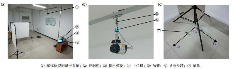 图 6. 实验室搭建测量与标定系统Figure 6. Build a measurement and calibration system in the laboratory表 2. 标定实验求得的四组特殊解Table 2. Four special solutions obtained by calibration experiments
特殊解 (x2, y2, z2)/mm (x1, y1, z1)/mm o2 (0, 0, 0) (1745.17, 1180.29, 2693.93) E (1168.95, 0, 0) (1764.64, 11.68, 2714.34) F (0, 1728.22, 0) (17.27, 1151.21221, 2677.68) G (0, 0, 2667.77) (1771.02, 1134.13, 26.68) | Show TableDownLoad:
CSV
将表 2中数据带入式(3),最终解得矩阵T得:
T=[0.017−0.9980.0101745.167−0.999−0.017−0.0171180.2910.017−0.009−0.9992693.9270001]。 4.2 模拟车体测量实验
为了验证标定结果和测量系统测量结果的实用性,用泡沫制作了一个类似车斗的模型作为被测件,如图 7所示。先用激光跟踪仪测得模拟车斗的长宽高作为车斗大小的实际值,再用组建的车体位姿测量系统对模拟车斗进行三维扫描测量,通过点云分割、去噪等处理,提取出车斗底部四个角点以及车帮上的部分点,如图 8所示。经过多次测量计算出车体大小位置参数的平均值和车体实际参数进行对比,结果如表 3所示。
表 3. 模拟车体测量结果Table 3. The result of measuring the simulated body测量次数 车斗长/mm 车斗宽/mm 车斗高/mm A点坐标/mm ω/(°) 1 2024.8 1824.3 510.7 (2360.4, 1220.8, 4.7) 0.2 2 2015.9 1820.1 509.6 (2367.2, 1219.7, 3.9) 0.13 3 2020.1 1822.7 510.6 (2359.7, 1225.1, 5.9) 0.18 4 2022.6 1826.5 514.3 (2362.4, 1227.3, 3.5) 0.17 真实值 2009.5 1812.4 502.3 (2371.2, 1214.3, 0) 0.02 最大误差 15.3 14.1 12 两点相距16.8 0.18 | Show TableDownLoad:
CSV
表 3中测量结果表明车斗模型测量值和实际值之间最大测量误差为16.8 mm,在激光雷达测量误差±30 mm之内,位姿角度测量最大误差为0.18°,完全满足实际测量的精度要求。
4.3 真实车体测量实验
将车体位姿测量系统搭建到室外,测量真实车体如图 9所示,经过多次测量,选取其中误差最大的一组数据如表 4所示。结果表明,该测量系统最大长度测量误差为26.4 mm,最大角度测量误差为0.18°,完全满足智能装车系统的装车要求。
5. 结论
本文立足于解决袋装物料自动装车前载货车辆车体位姿的测量问题,组建了基于二维激光雷达的车体测量系统,建立了系统数学模型。针对现有激光雷达三维测量系统测量范围小、标定过程复杂等问题,以321坐标系建立法为基础,提出了一种基于三平面标定板的系统参数标定方法。在实验室搭建测量系统进行标定实验以及模拟车体测量实验,同时在室外测量了真实车体,结果表明,车体位姿测量系统的测量精度完全满足智能装车的测量要求。但由于雷达自身误差较大以及不同物体对激光的反射效果差异较大等缘故,使测量结果仍存在一定的测量误差,故该系统的测量精度还需通过后续的研究进一步提高。
-
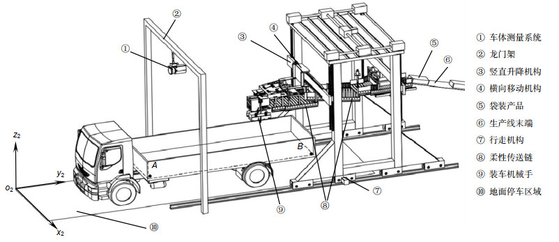
图 1 智能装车机器人系统总体结构示意图
Figure 1. Schematic diagram of the overall structure of the intelligent loading robot system
图 6 实验室搭建测量与标定系统
Figure 6. Build a measurement and calibration system in the laboratory
表 1 四组特殊解
Table 1. Four sets of special solutions
特殊解 (x2, y2, z2) (x1, y1, z1) 第一组 (0, 0, 0) (x11, y11, z11) 第二组 (x21, 0, 0) (x12, y12, z12) 第三组 (0, y21, 0) (x13, y13, z13) 第四组 (0, 0, z21) (x14, y14, z14)
下载: 导出CSV
表 2 标定实验求得的四组特殊解
Table 2. Four special solutions obtained by calibration experiments
特殊解 (x2, y2, z2)/mm (x1, y1, z1)/mm o2 (0, 0, 0) (1745.17, 1180.29, 2693.93) E (1168.95, 0, 0) (1764.64, 11.68, 2714.34) F (0, 1728.22, 0) (17.27, 1151.21221, 2677.68) G (0, 0, 2667.77) (1771.02, 1134.13, 26.68)
下载: 导出CSV
表 3 模拟车体测量结果
Table 3. The result of measuring the simulated body
测量次数 车斗长/mm 车斗宽/mm 车斗高/mm A点坐标/mm ω/(°) 1 2024.8 1824.3 510.7 (2360.4, 1220.8, 4.7) 0.2 2 2015.9 1820.1 509.6 (2367.2, 1219.7, 3.9) 0.13 3 2020.1 1822.7 510.6 (2359.7, 1225.1, 5.9) 0.18 4 2022.6 1826.5 514.3 (2362.4, 1227.3, 3.5) 0.17 真实值 2009.5 1812.4 502.3 (2371.2, 1214.3, 0) 0.02 最大误差 15.3 14.1 12 两点相距16.8 0.18
下载: 导出CSV
-
参考文献
[1] 王亚军.自动装车机的结构设计和研究[D].合肥: 中国科学技术大学, 2018: 1-4.
Wang Y J.Structure design and research of automatic loader[D].Hefei: University of Science and Technology of China, 2018: 1-4.
[2] 谢震.粉粒料袋包装货物全自动码垛装车系统的研制[D].哈尔滨: 哈尔滨工业大学, 2016: 3-7.
Xie Z.Research of automatic truck loading system for bag packaged power and granule[D].Harbin: Harbin Institute of Technology, 2016: 3-7.
[3] 黄金凤, 武金艺, 肖景金, 等.水泥装车机器人结构设计与分析[J].机械设计与制造, 2016(5):136-140. doi: 10.3969/j.issn.1001-3997.2016.05.036
Huang J F, Wu J Y, Xiao J J, et al.Structure design and movement simulation of cement loading robot[J].Machinery Design & Manufacture, 2016(5):136-140. doi: 10.3969/j.issn.1001-3997.2016.05.036
[4] 黄风山, 马帅, 薛泽.旋转二维激光雷达测量系统及其标定方法[J].光电子·激光, 2018, 29(9):987-995. http://www.wanfangdata.com.cn/details/detail.do?_type=perio&id=gdzjg201809011
Huang F S, Ma S, Xue Z.A rotating two-dimensional laser radar measurement system and the calibration method[J].Journal of Optoelectronics·Laser, 2018, 29(9):987-995. http://www.wanfangdata.com.cn/details/detail.do?_type=perio&id=gdzjg201809011
[5] 韩栋斌, 徐友春, 李华, 等.基于手眼模型的三维激光雷达外参数标定[J].光电工程, 2017, 44(8):798-804. doi: 10.3969/j.issn.1003-501X.2017.08.006
Han D B, Xu Y C, Li H, et al.Calibration of extrinsic parameters for three-dimensional lidar based on hand-eye model[J].Opto-Electronic Engineering, 2017, 44(8):798-804. doi: 10.3969/j.issn.1003-501X.2017.08.006
[6] 贺俊吉, 史立.散货自动装船检测系统[J].光电工程, 2009, 36(6):52-56, 119. doi: 10.3969/j.issn.1003-501X.2009.06.011
He J J, Shi L.Inspecting system for auto-loading of bulk cargo[J].Opto-Electronic Engineering, 2009, 36(6):52-56, 119. doi: 10.3969/j.issn.1003-501X.2009.06.011
[7] 陈贵宾, 高振海, 何磊.车载三维激光雷达外参数的分步自动标定算法[J].中国激光, 2017, 44(10):249-255. http://www.wanfangdata.com.cn/details/detail.do?_type=perio&id=zgjg201710032
Chen G B, Gao Z H, He L.Step-by-step automatic calibration algorithm for exterior parameters of 3D lidar mounted on vehicle[J].Chinese Journal of Lasers, 2017, 44(10):249-255. http://www.wanfangdata.com.cn/details/detail.do?_type=perio&id=zgjg201710032
[8] 杨兴雨, 苏金善, 王元庆, 等.大视场线阵推扫激光3D成像雷达光束整形[J].光电工程, 2016, 43(4):89-94. doi: 10.3969/j.issn.1003-501X.2016.04.015
Yang X Y, Su J S, Wang Y Q, et al.Lined push-room laser 3D imaging radar with large field beam shaping[J].Opto-Electronic Engineering, 2016, 43(4):89-94. doi: 10.3969/j.issn.1003-501X.2016.04.015
[9] 马帅.袋装物料智能装车系统关键技术研究[D].石家庄: 河北科技大学, 2018: 5-7.
Ma S.Study on key technology of intelligent loading system for bagged materials[D].Shijiazhuang: Hebei University of Science & Technology, 2018: 5-7.
[10] 项志宇.快速三维扫描激光雷达的设计及其系统标定[J].浙江大学学报(工学版), 2006, 40(12):2130-2133. doi: 10.3785/j.issn.1008-973X.2006.12.024
Xiang Z Y.Fast 3D scanning laser radar system design and calibration[J].Journal of Zhejiang University(Engineering Science), 2006, 40(12):2130-2133. doi: 10.3785/j.issn.1008-973X.2006.12.024
[11] 彭梦, 蔡自兴.一种基于双平行平面的激光雷达和摄像机标定方法[J].中南大学学报(自然科学版), 2012, 43(12):4735-4742. http://d.old.wanfangdata.com.cn/Periodical/zngydxxb201212023
Peng M, Cai Z X.A practical method for calibration of laser radar and camera based on double parallel planes[J].Journal of Central South University (Science and Technology), 2012, 43(12):4735-4742. http://d.old.wanfangdata.com.cn/Periodical/zngydxxb201212023
[12] 石路.三维激光测量系统标定方法的理论与实验研究[D].上海: 上海交通大学, 2010: 22-34.
Shi L.Theoretical and experiment research on the calibration method of 3D laser scanning system[D].Shanghai: Shanghai Jiao Tong University, 2010: 22-34.
[13] 俞奇奇, 崔振山.一种基于2D激光雷达的扫描系统标定方法[J].激光与红外, 2017, 47(10):1234-1237. doi: 10.3969/j.issn.1001-5078.2017.10.008
Yu Q Q, Cui Z S.Calibration of scanning system based on 2D laser radar[J].Laser & Infrared, 2017, 47(10):1234-1237. doi: 10.3969/j.issn.1001-5078.2017.10.008
施引文献
期刊类型引用(11)
1. 庞广富,余鹏. 改进AMCL最优位姿估计的机器人室内定位控制. 信息技术. 2024(04): 143-148 .  百度学术
百度学术
2. 何小英,王旭. 激光雷达和视觉技术的机器人移动位置跟踪系统. 激光杂志. 2023(01): 232-237 . 百度学术
3. 龚子恺,席燕辉,沈大勇. 激光雷达外参数的自动标定. 激光与光电子学进展. 2023(22): 291-299 . 百度学术
4. 虞静,黄陆君,唐海龙,黄贵余,陈光平. 面向自动装车的来车检测和规划系统. 应用激光. 2022(01): 91-100 . 百度学术
5. 李树青,邢鑫龙,林靖宇. 一种三维激光雷达系统标定方法. 激光与红外. 2022(02): 182-187 . 百度学术
6. 吴莲香,房玮. 激光传感器的多陷阱复杂环境机器人导航系统. 激光杂志. 2022(12): 231-236 . 百度学术
7. 李鹏,赵鲁燕. 激光雷达测距的机器人最优移动路径选择机制. 激光杂志. 2021(01): 183-186 . 百度学术
8. 张宏群,刘开辉,郑峰,陈佳力,陈思. 基于二维激光雷达植株高度测量系统的研究. 电子测量技术. 2021(04): 97-103 . 百度学术
9. 刘祎,刘萍,李守军. 激光雷达和神经网络相融合的机器人避障轨迹规划研究. 激光杂志. 2021(09): 175-178 . 百度学术
10. 葛亚明,胡一博,雷乔治,陈浩耀. ROS无人驾驶创新实验课程研究与教学实践. 实验技术与管理. 2020(06): 221-224 . 百度学术
11. 范本,胡祝敏,胡伦俊. 基于徕卡测量机器人的山区边坡地质失稳监测研究. 灾害学. 2020(03): 29-33 . 百度学术
其他类型引用(11)
-
访问统计


 点击扫一扫
点击扫一扫
图(8)
表(3)
计量
- 文章访问数: 11158
- PDF下载数: 3732
- 施引文献: 22