
 E-mail Alert
 RSS
RSS
Research on field calibration method of straightness in five-degree-of-freedom measurement
-
摘要
直线度现场标定是保证其在线测量精度的重要方法。在收发一体式激光五自由度测量结构的基础上,针对直线度现场标定中标定平台引入的阿贝误差和角锥棱镜成像误差,建立了直线度现场标定模型。根据该标定模型并结合五自由度测量装置的角度测量结果,提出一种直线度现场标定误差补偿方法。实验表明,该标定方法使标定系数误差减小到0.2%以内,有效提高了直线度现场标定精度。
Abstract
The field calibration of straightness is an important method to ensure the accuracy of on-line measurement. Based on the transceiver integrated laser five-degree-of-freedom measurement structure, the field calibration model was established aiming at the Abbe error, and the imaging error of retroreflector caused by the calibration platform. According to the calibration model and the angle measurement results of the five-degree-of-freedom measuring device, a compensation method of straightness calibration errors was proposed. Experimental results showed that the calibration coefficient error was within 0.2% when using the calibration method, and the calibration errors of straightness were effectively reduced. The calibration method made the error of calibration coefficient reduce to less than 0.2%, and effectively improved the accuracy of straightness field calibration.
-
Overview
Overview: The multi-degree-of-freedom measurement is one of the important methods to realize the rapid and high-precision measurement of geometric errors of machine tools. Straightness measurement, as an important part in the multi-degree-of-freedom measurement, directly affects the accuracy of error measurement of the machine tools. At present, the straightness measurement based on laser collimation has been widely used in multi-degree-of-freedom measurement systems. When the measuring device is applied in the field, the field calibration can effectively eliminate the system error caused by the installation and adjustment of the measuring device, change of environmental parameters, stress, and abrasion in the field application. But the precision and stability of the calibration platform are uncertain in the field calibration of straightness, so the calibration error caused by the calibration platform cannot be ignored.
In the five-degree-of-freedom measuring structure of laser transceiver, the straightness is measured based on the laser collimation principle, and the inverse reflection characteristics of the retroreflector. QPD1 (quadrant photodiode detector) is used to detect the location of the light spot. When using the laser interferometer to calibrate the straightness, the X-direction output and the Z-direction output of QPD1 need to be calibrated. In the field calibration of straightness, the angle of calibration platform would change. The Abbe error caused by the different measuring points of laser interferometer and straightness would affect the calibration accuracy, and it is determined by the Abbe deviation and the angle change of calibration platform. In addition, when the angle of calibration platform changes, the imaging error of retroreflector is part of the calibration errors according to the principle of parallel plate expansion of retroreflector. The field calibration model was established aiming at the calibration errors caused by the calibration platform. According to the calibration model and the angle measurement results of the five-degree-of-freedom measuring device, a compensation method of straightness calibration error was proposed.
In the calibration experiment, the X-direction output and Z-direction output of QPD1 in the five-degree-of-freedom measuring device was calibrated with laser interferometer. A low-precision calibration platform was used to simulate the field calibration environment, and a high-precision calibration platform with negligible angle change was used for comparison experiment. Experimental results showed that the calibration coefficient error of the X-direction straightness was reduced from 3.5% to less than 0.1% and the calibration coefficient error of the Z-direction straightness was reduced from 4% to less than 0.2%. The Abbe error and the imaging error of retroreflector were eliminated and the calibration accuracy of straightness was effectively improved.
-
1. 引言
多自由度的测量是实现快速、高精度检测机床几何误差的重要手段之一[1]。直线度测量作为多自由度测量中的关键环节,直接影响机床空间误差测量[2-4],因此研究直线度测量及标定方法具有重要意义。
目前,基于激光准直的直线度测量方法[5]已被广泛应用到多自由度测量系统中[6-9]。Ni等人[10]在多自由度测量系统中采用了激光偏振和激光准直相结合的方法,实现了直线度误差测量,在±50 μm标定范围内标定残差为±1.0 μm。冯其波教授等人[11-15]在激光准直的基础上提出激光光束漂移共路补偿的方法,在±100 μm标定范围内直线度标定标准差为0.5 μm。以上研究中的直线度标定均在实验室条件下使用高精度标定平台完成,未分析标定过程中的误差。为实现机床几何误差的现场在线测量,保证测量装置在现场环境中的测量精度尤其重要。现场标定可以有效消除现场应用中测量装置安装与调节、环境参数改变、应力与磨损等引入的系统误差,保证系统测量精度。但现场标定时受工业环境影响,标定平台的精度及稳定性无法保证,引入的标定误差不可忽略。
本文在激光收发一体式五自由度测量结构的基础上,分析了直线度现场标定中激光干涉仪测量点与直线度测量点不重合产生的阿贝误差与角锥棱镜产生的成像误差,建立了直线度现场标定模型。根据该标定模型并结合五自由度测量装置的角度测量结果,提出了一种直线度标定误差补偿方法,在不增加测量复杂度的同时,提高现场标定精度,并进行了实验验证。
2. 五自由度测量结构中直线度测量原理
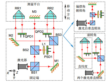
五自由度测量结构采用激光器发射与探测器接收一体化设计,如图 1所示。激光器出射的激光经分光镜BS1(beam splitter)反射与分光镜BS2透射到平面镜M3(mirror)上。回射的激光经BS2反射后,通过透镜L1(lens)聚焦到位置敏感探测器PSD1(position sensitive device)上,构成激光自准直模块,测量俯仰角和偏摆角。从BS1透射的激光经平面镜M1反射后,被分光镜BS3分成两束。一束激光经过平面镜M2反射到角锥棱镜RR1(retro-reflector),由于角锥棱镜特有的逆向反射特性,使光线平行回射到四象限光电探测器QPD1(quadrant photodiode detector)上。另一束激光直接经角锥棱镜RR2回射到四象限光电探测器QPD2上,构成两个激光准直模块。利用任意一个激光准直模块测量二维直线度,两个激光准直模块配合使用时,测量滚转角。
选取RR1与QPD1作为测量二维直线度的激光准直模块,并按照高斯分布的圆形光斑建立了QPD测量模型[16]。光斑质心相对QPD1中心产生偏移时,四个象限产生相应光强大小的光电流IA、IB、IC和ID,光斑在QPD1的X向位移和Z向位移ΔxLQ1和ΔzLQ1为
{ΔxLQ1=kxΔxQ1=kxIA+ID−IB−ICIA+IB+IC+IDΔzLQ1=kzΔzQ1=kzIA+IB−IC−IDIA+IB+IC+ID, (1) 其中:ΔxQ1和ΔzQ1分别定义为QPD1的X向输出和Z向输出,kx和kz为待标定的系数。
当测量平台移动时,X轴方向的直线度误差δx和Z轴方向的直线度误差δz可以表示为
δx=ΔxRR1=ΔxLQ12=kxΔxQ12, (2) δz=ΔzRR1=ΔzLQ12=kzΔzQ12, (3) 其中:ΔxRR1和ΔzRR1分别为RR1在X向和Z向的位移。
3. 现场标定误差分析
3.1 直线度标定方法
直线度标定过程中需要对QPD1的X向输出和Z向输出分别标定。QPD1的X向输出标定原理图如图 2所示,RR1与激光干涉仪角锥棱镜RR3放置在标定平台上,同时对标定平台X向位移进行测量,从而实现激光干涉仪对QPD1的X向输出的标定。当标定平台在X向移动时,激光干涉仪测量值Δdx可以表示为
 图 2. QPD1的X向输出标定原理图Figure 2. Schematic diagram of X-direction output calibration of QPD1
Δdx=ΔxRR1=ΔxLQ12=kxΔxQ12。 (4) QPD1的Z向输出标定原理图如图 3所示,当标定平台在Z向移动时,激光干涉仪测量值为Δdz,QPD1的Z向输出标定模型为
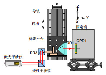 图 3. QPD1的Z向输出标定原理图Figure 3. Schematic diagram of Z-direction output calibration of QPD1
Δdz=ΔzRR1=ΔzLQ12=kzΔzQ12。 (5) 但在现场标定时,受工业环境影响,标定平台的精度及稳定性无法保证,其角度变化引入的标定误差是影响标定精度的重要因素。
3.2 现场标定中的阿贝误差
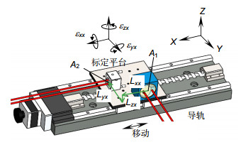
QPD1的X向输出标定时,设标定平台移动时产生偏摆角εzx、俯仰角εyx和滚转角εxx,如图 4所示。设激光干涉仪测量点为RR3前表面中点A2(x2,y2,z2),直线度测量点为RR1前表面中点A1(x1,y1,z1),由于激光干涉仪测量点与直线度测量点不重合,标定过程中存在三个方向的阿贝偏位Lxx、Lyx和Lzx,即:
[LxxLyxLzx]=[x2−x1y2−y1z2−z1]。 (6) 考虑角度和阿贝偏位的影响,并忽略二阶小量,QPD1的X向输出标定中的阿贝误差为
[δxx1δyx1δzx1]=[0−εzxεyxεzx0−εxx−εyxεxx0][LxxLyxLzx]=[−εzxLyx+εyxLzxεzxLxx−εxxLzx−εyxLxx+εxxLyx]。 (7) 其中:δxx1、δyx1、δzx1分别为X向、Y向和Z向的阿贝误差。
对于QPD1的X向输出标定,影响标定精度的阿贝误差为δxx1,表示为
δxx1=−εzxLyx+εyxLzx。 (8) QPD1的Z向输出标定中,设标定平台产生偏摆角εzx、俯仰角εyz和滚转角εzz,标定过程中激光干涉仪测量点与直线度测量点在三个方向上的阿贝偏位为Lxz、Lyz和Lzz,考虑角度和阿贝偏位的影响,并忽略二阶小量,QPD1的Z向输出标定中的阿贝误差δzz1为
δzz1=−εyzLxz+εxzLyz。 (9) 3.3 现场标定中的角锥棱镜成像误差
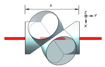
光线经过RR1时,根据棱镜展开原理,RR1的等效平行平板展开图如图 5所示。
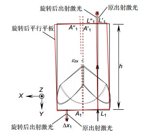
QPD1的X向输出标定时,偏摆角εzx造成角锥棱镜的出射激光X向偏移,影响QPD1的X向输出,如图 6所示。直线度测量点A1的阿贝误差已考虑,故认为此点为RR1的旋转中心,未旋转前平行平板中心线为A1A′1,激光从L1点入射后从L′1点出射,旋转后平行平板中心线为A1A1″,激光出射点偏移到{L''_1},考虑RR1的成像误差,光斑在QPD1的X向位移变化量\Delta {x_l}为
\Delta {x_l} = \left| {{{A'}_1}{{A''}_1}} \right| - \left| {{{L'}_1}{{L''}_1}} \right| = \frac{{h \cdot {\varepsilon _{zx}}}}{n}, (10) 其中:n为角锥棱镜RR1材料的折射率,h为等效平行平板长度。
角锥棱镜RR3角度变化对激光干涉仪X向位移测量值影响为二阶小量,可以忽略。
QPD1的Z向输出标定时,考虑RR1的成像误差,光斑在QPD1的Z向位移变化量\Delta {z_l}为
\Delta {z_l} = h \cdot {\varepsilon _{xz}}/n。 (11) 3.4 二维直线度现场标定模型
综合阿贝误差与角锥棱镜的成像误差,QPD1的X向输出和Z向输出标定模型为
\left\{ \begin{gathered} \Delta {{d'}_x}{\rm{ = }}\frac{{{k_x}\Delta {x_{{\rm{Q}}1}}}}{2}{\rm{ + }}{\varepsilon _{zx}} \cdot \left( {\frac{h}{{2n}} - {L_{yx}}} \right) + {\varepsilon _{yx}}{L_{zx}} \\ \Delta {{d'}_z}{\rm{ = }}\frac{{{k_z}\Delta z_{{\rm{Q}}1}^{}}}{2} + {\varepsilon _{xz}} \cdot \left( {\frac{h}{{2n}} - {L_{yz}}} \right){\rm{ + }}{\varepsilon _{yz}}{L_{xz}} \\ \end{gathered} \right., (12) 其中:\Delta {d'_x}和\Delta {d'_z}分别为QPD1 X向输出和Z向输出标定时激光干涉仪测量值。
对于QPD1 X向输出标定或Z向输出标定,为补偿标定过程中的阿贝误差与角锥棱镜成像误差,使用五自由度测量装置的自准直模块测量标定平台的偏摆角{\varepsilon _{zx}}或{\varepsilon _{xz}},作为标定的参数之一。但对于标定平台的俯仰角{\varepsilon _{yx}}或{\varepsilon _{yz}},在直线度标定过程中无法用五自由度测量装置测量,为了在不增加测量复杂度的同时消除阿贝误差,需保证阿贝偏位Lzx或Lxz为0。
4. 实验验证与分析
4.1 X向直线度标定实验
对QPD1的X向输出进行标定实验,首先采用角度变化可以忽略的高精度标定平台进行标定实验,然后采用精度较差的标定平台模拟现场标定环境,进行标定实验。对比两次标定实验,验证标定模型和补偿方法的有效性。
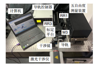
QPD1的X向输出标定系统如图 7,激光干涉仪作为位移测量标准,导轨控制器控制标定平台移动,角锥棱镜RR1、RR3和反射镜M3放在标定平台上,其中M3用于测量导轨偏摆角,RR1的制造材料为N-BK7玻璃,折射率n=1.515,等效平行平板长h=84 mm。
4.1.1 高精度标定平台标定实验
采用高精度标定平台,用激光干涉仪对五自由度测量装置中QPD1的X向输出进行标定,标定范围为±125 μm。高精度标定平台角度变化不超过±5 μm/m,保证Lzx和h/2n - {L_{yx}}在±10 mm以内,引入的直线度标定误差不超过0.1 μm,可以忽略。标定数据和标定结果如表 1和图 8所示,系数kx的标定值为1.1488,标定残差在±1 μm以内。
表 1. 高精度标定平台标定数据Table 1. Calibration data of high precision calibration platform激光干涉仪测量值∆dx'/μm QPD1 X向输出测量值∆xQ -125.1 -109.192 -99.48 -86.972 -74.77 -65.187 -49.36 -42.669 -24.95 -21.426 0.00 0.000 25.58 21.682 49.99 42.886 75.41 65.364 100.15 87.189 125.23 109.037 | Show Table DownLoad:
CSV
DownLoad:
CSV
4.1.2 低精度标定平台标定实验
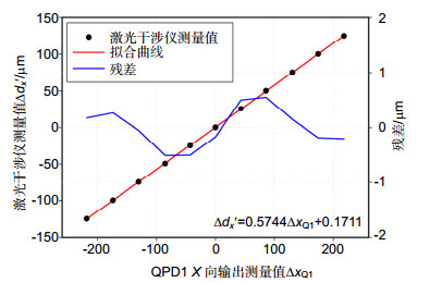
采用低精度标定平台模拟现场标定环境,进行标定实验。标定平台偏摆角{\varepsilon _{zx}}在±125 μm标定范围内变化超过1000 μm/m。实验在保证阿贝偏位Lzx为0 mm,Lyx固定的条件下用激光干涉仪对五自由度测量装置中QPD1的X向输出进行标定,同时用五自由度测量装置测量标定平台的偏摆角{\varepsilon _{zx}}。标定数据如表 2所示。图 9(a)为未补偿偏摆角引入的阿贝误差和角锥棱镜成像误差时的标定结果,对测量结果进行二元线性回归,得到补偿后的标定结果,如图 9(b)所示。
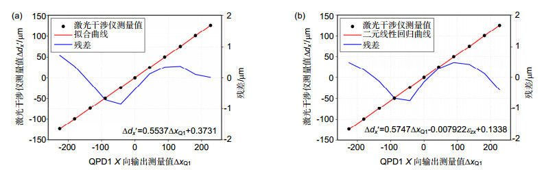 图 9. 低精度标定平台标定结果。(a)补偿前; (b)补偿后Figure 9. Calibration results of low precision calibration platform. (a) Before compensation; (b) After compensation表 2. 低精度标定平台标定数据Table 2. Calibration data of low precision calibration platform
激光干涉仪测量值∆dx'/μm QPD1 X向输出测量值∆xQ 偏摆角测量值εzx/(μm/m) -123.85 -112.824 -658 -99.4 -90.429 -525 -74.05 -67.054 -380 -49.66 -44.541 -260 -24.02 -21.265 -129 0.00 0.000 0 24.98 22.105 107 50.17 44.647 223 76.21 68.135 336 101.08 90.835 452 126.08 113.493 518 | Show TableDownLoad:
CSV
标定结果表明,补偿前系数kx的标定值为1.1074,与采用高精度标定平台时系数kx的标定值相差0.0414,即标定系数误差在3.5%左右,则在±125 μm范围内,由系数kx引入的标定误差最大为10 μm,严重影响标定精度。补偿后系数kx的标定值为1.1494,与采用高精度标定平台时系数kx的标定值相差0.0006,即标定系数误差在0.1%以内,则在±125 μm范围内,由系数kx引入的标定误差最大为0.15 μm,可以忽略。补偿阿贝误差和角锥棱镜成像误差后,标定系数误差从3.5%减少到0.1%以内,有效提高了标定精度。
4.2 Z向直线度标定实验
对QPD1的Z向输出进行标定实验,标定过程与X向直线度标定实验相同,QPD1的Z向输出标定系统如图 10所示。
4.2.1 高精度标定平台标定实验
采用高精度标定平台,用激光干涉仪对五自由度测量装置中QPD1的Z向输出进行标定,标定范围为±125 μm。标定数据和标定结果如表 3和图 11所示,系数kz的标定值为1.1060,直线度标定残差在±1 μm以内。
表 3. 高精度标定平台标定数据Table 3. Calibration data of high precision calibration platform激光干涉仪测量值∆dz'/μm QPD1 Z向输出测量值∆zQ -124.65 -112.888 -100.2 -90.493 -74.85 -67.118 -50.46 -44.305 -24.82 -21.329 -0.8 -0.064 24.18 22.041 49.37 44.583 75.41 68.071 100.28 91.171 125.28 113.929 | Show TableDownLoad:
CSV
4.2.2 低精度标定平台标定实验
采用低精度标定平台模拟现场标定环境,进行标定实验。保证阿贝偏位Lxz为0 mm,Lyz固定的条件下用激光干涉仪对五自由度测量装置中QPD1的Z向输出进行标定,同时用五自由度测量装置测量标定平台的偏摆角{\varepsilon _{xz}}。标定数据如表 4所示。图 12(a)为未补偿偏摆角引入的阿贝误差和角锥棱镜成像误差时的标定结果,对测量结果进行二元线性回归,得到补偿后的标定结果,如图 12(b)所示。
表 4. 低精度标定平台标定数据Table 4. Calibration data of low precision calibration platform激光干涉仪测量值∆dz'/μm QPD1 Z向输出测量值∆zQ 偏摆角测量值εxz/(μm/m) -125.07 -118.527 -203 -100.21 -94.950 -207 -74.75 -70.262 -153 -50.16 -46.593 -108 -25.01 -22.453 -58 -0.2 1.161 -3 24.99 24.487 27 50.41 47.717 58 75.29 70.558 86 100.41 93.942 111 124.89 117.077 134 | Show TableDownLoad:
CSV
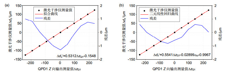 图 12. 低精度标定平台标定结果。(a)补偿前;(b)补偿后Figure 12. Calibration results of low precision calibration platform. (a) Before compensation; (b) After compensation
标定结果表明,补偿前系数kz的标定值为1.0624,与采用高精度标定平台时系数kz的标定值相差0.0436,即标定系数误差在4%左右,则在±125 μm范围内,由系数kz引入的标定误差最大为10 μm以上,严重影响标定精度。补偿后系数kz的标定值为1.1082,与采用高精度标定平台时系数kz的标定值相差0.0022,即标定系数误差在0.2%以内,则在±125 μm范围内,由系数kz引入的标定误差最大为0.5 μm。补偿阿贝误差和角锥棱镜成像误差后,标定误差从4%减少到0.2%以内,有效提高了标定精度。
4.3 直线度测量对比实验
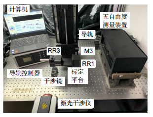
为验证标定结果,使用激光干涉仪和五自由度测量装置同时测量导轨的直线度,如图 13所示。导轨移动距离为200 mm,每隔20 mm测量一组数据,实验结果如图 14所示。
 图 13. 二维直线度测量对比实验系统Figure 13. Measurement and comparison experiment system of two-dimension straightness
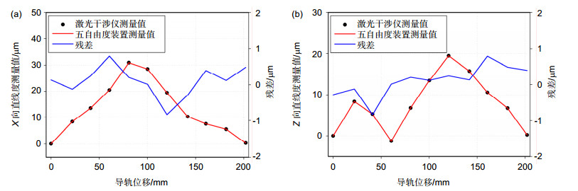 图 14. 二维直线度测量对比实验结果。(a) X向直线度;(b) Z向直线度Figure 14. Measurement and comparison experiment results of two-dimension straightness. (a) Straightness along X axis; (b) Straightness along Z axis
实验结果表明,残差在±1 μm以内,验证了标定方法的有效性。
5. 结论
理论分析和实验结果表明,利用该标定方法可以基本消除标定平台自身角度变化引入的阿贝误差与角锥棱镜成像误差,有效提高了直线度标定精度。利用五自由度测量装置本身的角度测量结果补偿直线度标定误差,在不增加测量复杂度的同时,提高了标定精度。实验中利用低精度的标定平台模拟现场标定环境,实现了高精度标定,在一定程度上证明了该现场标定方法的有效性,但仍存在一定局限性,需在工业现场做进一步验证,实现此标定方法的推广应用。
-
图 2 QPD1的X向输出标定原理图
Figure 2. Schematic diagram of X-direction output calibration of QPD1
图 3 QPD1的Z向输出标定原理图
Figure 3. Schematic diagram of Z-direction output calibration of QPD1
图 9 低精度标定平台标定结果。(a)补偿前; (b)补偿后
Figure 9. Calibration results of low precision calibration platform. (a) Before compensation; (b) After compensation
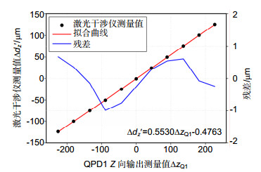
图 11 高精度标定平台标定结果
Figure 11. Calibration results of high precision calibration platform
图 12 低精度标定平台标定结果。(a)补偿前;(b)补偿后
Figure 12. Calibration results of low precision calibration platform. (a) Before compensation; (b) After compensation
图 13 二维直线度测量对比实验系统
Figure 13. Measurement and comparison experiment system of two-dimension straightness
图 14 二维直线度测量对比实验结果。(a) X向直线度;(b) Z向直线度
Figure 14. Measurement and comparison experiment results of two-dimension straightness. (a) Straightness along X axis; (b) Straightness along Z axis
表 1 高精度标定平台标定数据
Table 1. Calibration data of high precision calibration platform
激光干涉仪测量值∆dx'/μm QPD1 X向输出测量值∆xQ -125.1 -109.192 -99.48 -86.972 -74.77 -65.187 -49.36 -42.669 -24.95 -21.426 0.00 0.000 25.58 21.682 49.99 42.886 75.41 65.364 100.15 87.189 125.23 109.037
下载: 导出CSV
表 2 低精度标定平台标定数据
Table 2. Calibration data of low precision calibration platform
激光干涉仪测量值∆dx'/μm QPD1 X向输出测量值∆xQ 偏摆角测量值εzx/(μm/m) -123.85 -112.824 -658 -99.4 -90.429 -525 -74.05 -67.054 -380 -49.66 -44.541 -260 -24.02 -21.265 -129 0.00 0.000 0 24.98 22.105 107 50.17 44.647 223 76.21 68.135 336 101.08 90.835 452 126.08 113.493 518
下载: 导出CSV
表 3 高精度标定平台标定数据
Table 3. Calibration data of high precision calibration platform
激光干涉仪测量值∆dz'/μm QPD1 Z向输出测量值∆zQ -124.65 -112.888 -100.2 -90.493 -74.85 -67.118 -50.46 -44.305 -24.82 -21.329 -0.8 -0.064 24.18 22.041 49.37 44.583 75.41 68.071 100.28 91.171 125.28 113.929
下载: 导出CSV
表 4 低精度标定平台标定数据
Table 4. Calibration data of low precision calibration platform
激光干涉仪测量值∆dz'/μm QPD1 Z向输出测量值∆zQ 偏摆角测量值εxz/(μm/m) -125.07 -118.527 -203 -100.21 -94.950 -207 -74.75 -70.262 -153 -50.16 -46.593 -108 -25.01 -22.453 -58 -0.2 1.161 -3 24.99 24.487 27 50.41 47.717 58 75.29 70.558 86 100.41 93.942 111 124.89 117.077 134
下载: 导出CSV
-
参考文献
[1] 焦明星, 冯其波, 王鸣, 等.激光传感与测量[M].北京:科学出版社, 2014.
Jao M X, Feng Q B, Wang M, et al. Sensing and Measuring with Lasers[M]. Beijing: Science Press, 2014.
[2] 王明海, 娄志峰, 黄余彬, 等.一种导轨直线度与平行度测量系统的研究与应用[J].现代机械, 2018(5): 20–24. http://www.wanfangdata.com.cn/details/detail.do?_type=perio&id=xdjx201805005
Wang M H, Lou Z F, Huang Y B, et al. Research and application of a measurement system of the straightness and parallelism for guide rail[J]. Modern Machinery, 2018(5): 20–24. http://www.wanfangdata.com.cn/details/detail.do?_type=perio&id=xdjx201805005
[3] 金涛, 刘景林, 杨卫, 等.线性位移台直线度高精密外差干涉测量装置[J].光学 精密工程, 2018, 26(7): 1570–1577. http://www.wanfangdata.com.cn/details/detail.do?_type=perio&id=gxjmgc201807002
Jin T, Liu J L, Yang W, et al. High-precision straightness interferometer for linear moving stage[J]. Optics and Precision Engineering, 2018, 26(7): 1570–1577. http://www.wanfangdata.com.cn/details/detail.do?_type=perio&id=gxjmgc201807002
[4] 徐淼, 王新宽, 钱林弘.一种超精密大行程导轨直线度检测新方法[J].机床与液压, 2017, 45(10): 140–143. http://www.wanfangdata.com.cn/details/detail.do?_type=perio&id=jcyyy201710037
Xu M, Wang X K, Qian L H. A new method for measurement of straightness of ultra-precise guideway with large distance[J]. Machine Tool & Hydraulics, 2017, 45(10): 140–143. http://www.wanfangdata.com.cn/details/detail.do?_type=perio&id=jcyyy201710037
[5] 曹益平, 刘明健, 刘晓丽, 等.大尺度二维直线度测量仪的研制[J].光电工程, 2004, 31(9): 57–60. doi: 10.3969/j.issn.1003-501X.2004.09.015
Cao Y P, Liu M J, Liu X L, et al. Development of an instrument for measuring large range 2-D straightness[J]. Opto-Electronic Engineering, 2004, 31(9): 57–60. doi: 10.3969/j.issn.1003-501X.2004.09.015
[6] Huang P S, Ni J. On-line error compensation of coordinate measuring machines[J]. International Journal of Machine Tools and Manufacture, 1995, 35(5): 725–738. doi: 10.1016/0890-6955(95)93041-4
[7] Fan K C, Chen M J. A 6-degree-of-freedom measurement system for the accuracy of X-Y stages[J]. Precision Engineering, 2000, 24(1): 15–23. doi: 10.1016/S0141-6359(99)00021-5
[8] Kuang C F, Hong E, Ni J. A high-precision five-degree-of-freedom measurement system based on laser collimator and interferometry techniques[J]. Review of Scientific Instruments, 2007, 78(9): 095105. doi: 10.1063/1.2786272
[9] Bao C C, Li J K, Feng Q B, et al. Error-compensation model for simultaneous measurement of five degrees of freedom motion errors of a rotary axis[J]. Measurement Science and Technology, 2018, 29(7): 075004. doi: 10.1088/1361-6501/aac119
[10] Ni J, Huang P S, Wu S M. A multi-degree-of-freedom measuring system for CMM geometric errors[J]. Journal of Manufacturing Science and Engineering, 1992, 114(3): 362–369. http://www.wanfangdata.com.cn/details/detail.do?_type=perio&id=JAKO199411919530537
[11] Kuang C F, Feng Q B, Zhang B, et al. A four-degree-of-freedom laser measurement system (FDMS) using a single-mode fiber-coupled laser module[J]. Sensors and Actuators A: Physical, 2005, 125(1): 100–108. doi: 10.1016/j.sna.2005.05.022
[12] Feng Q B, Zhang B, Cui C X, et al. Development of a simple system for simultaneously measuring 6DOF geometric motion errors of a linear guide[J]. Optics Express, 2013, 21(22): 25805–25819. doi: 10.1364/OE.21.025805
[13] 由凤玲, 冯其波, 张斌.基于共路光线漂移补偿的直线度测量[J].光学 精密工程, 2011, 19(3): 515–519. http://www.wanfangdata.com.cn/details/detail.do?_type=perio&id=gxjmgc201103003
You F L, Feng Q B, Zhang B. Straightness error measurement based on common-path compensation for laser beam drift[J]. Optics and Precision Engineering, 2011, 19(3): 515–519. http://www.wanfangdata.com.cn/details/detail.do?_type=perio&id=gxjmgc201103003
[14] 吕勇, 冯其波, 刘立双, 等.基于多准直光的六自由度测量方法[J].红外与激光工程, 2014, 43(11): 3597–3602. http://www.wanfangdata.com.cn/details/detail.do?_type=perio&id=hwyjggc201411016
Lv Y, Feng Q B, Liu L S, et al. Six-degree-of-freedom measurement method based on multiple collimated beams[J]. Infrared and Laser Engineering, 2014, 43(11): 3597–3602. http://www.wanfangdata.com.cn/details/detail.do?_type=perio&id=hwyjggc201411016
[15] 匡萃方, 冯其波, 刘斌, 等.一种共路补偿激光漂移的直线度测量方法[J].光电工程, 2005, 32(4): 32–34, 38. doi: 10.3969/j.issn.1003-501X.2005.04.009
Kuang C F, Feng Q B, Liu B, et al. Measuring straightness method with common path compensation for laser drift[J]. Opto-Electronic Engineering, 2005, 32(4): 32–34, 38. doi: 10.3969/j.issn.1003-501X.2005.04.009
[16] Saito Y, Gao W, Kiyono S. A single lens micro-angle sensor[J]. International Journal of Precision Engineering and Manufacturing, 2007, 8(2): 14–19. http://www.wanfangdata.com.cn/details/detail.do?_type=perio&id=JAKO200714539080852
施引文献
期刊类型引用(3)
1. 张聪,刘文正,段发阶,傅骁,王新星. 长导轨五自由度测量中直线度精度提升方法与优化设计. 光学精密工程. 2022(20): 2467-2478 .  百度学术
百度学术
2. 吴天凤,李莉,杨洪涛. 数控机床XY工作台单向运动二维阿贝误差分析与建模. 光学精密工程. 2021(02): 329-337 . 百度学术
3. 高洁,郭贤斌,焦晓光,刘冠宇,王瑞. 长基线天线六自由度激光测量技术. 制导与引信. 2021(04): 39-44 . 百度学术
其他类型引用(3)
-
访问统计

 点击扫一扫
点击扫一扫
图(14)
表(4)
计量
- 文章访问数: 8028
- PDF下载数: 1958
- 施引文献: 6