Research on high-precision dynamic focus detection technology of differential critical angle method
-
摘要
基于临界角检焦技术具有光能量损耗小、组装相对简单、调试相对容易、系统分辨率高等特点,当引入差动信号处理技术,可放大提取的检焦信号,提升检测灵敏度和提高检焦曲线的光滑度,同时可实现更大的焦面检测范围,减少由于基底本身存在不平整影响到的检焦误差。本论文首先从差动临界角法检焦技术的基本原理出发,通过Fresnel公式和牛顿公式得到离焦量与离焦信号的关系。其次搭建差动临界角法检焦验证系统,利用四象限光电探测器采集单个临界角棱镜的离焦信号,并对两个垂直放置的四象限光电探测器接收到的离焦信号进行差动计算,以获得差动
K 值大小与离焦量z 之间的关系。实验结果表明:采用波长532 nm的激光,数值孔径0.3的投影物镜时,检焦线性范围可达22 μm;采用数值孔径0.45的投影物镜时,检焦线性范围可达14 μm,差动临界角检焦法分辨率可达25 nm。Abstract
Based on the characteristics of low light energy loss, relatively simple assembly, relatively easy debugging, and high system resolution, the critical angle focusing technology can be introduced to amplify the extracted focusing signal, improve the detection sensitivity and the smoothness of the focusing curve, and at the same time achieve a larger focal plane detection range, reducing the focusing error affected by the unevenness of the substrate itself. This paper first starts from the basic principle of the differential critical angle focusing technology and obtains the relationship between the defocus amount and the defocus signal through the Fresnel formula and the Newton formula. Secondly, a differential critical angle focusing verification system is built, a four-quadrant photodetector collects the defocus signal of a single critical angle prism, and the defocus signals received by two vertically placed four-quadrant photodetectors are differentially calculated to obtain the relationship between the differential
K value and the defocus amountz . The experimental results show that when a wavelength of 532 nm laser and a numerical aperture of 0.3 projection objective are used, the focusing linear range can reach 22 μm. When a numerical aperture of 0.45 projection objective is used, the focusing linear range can reach 14 μm, and the resolution of the differential critical angle focusing method can reach 25 nm. -
Overview
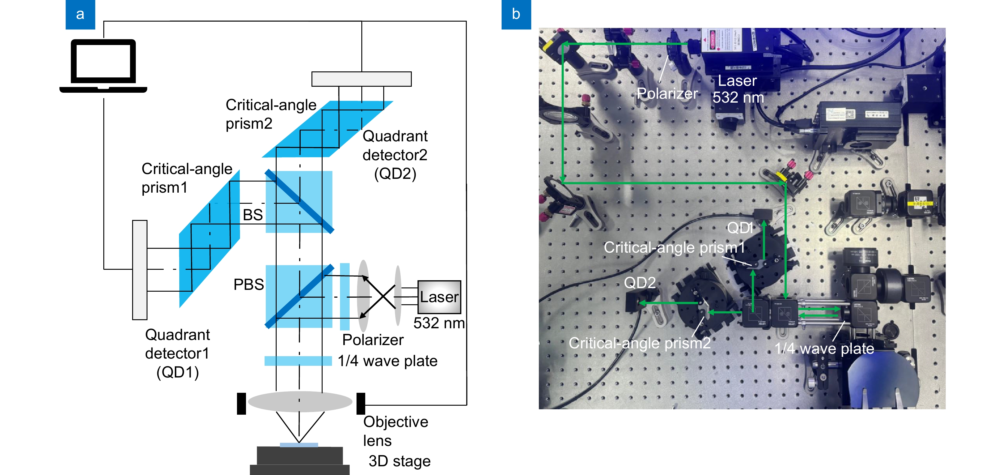
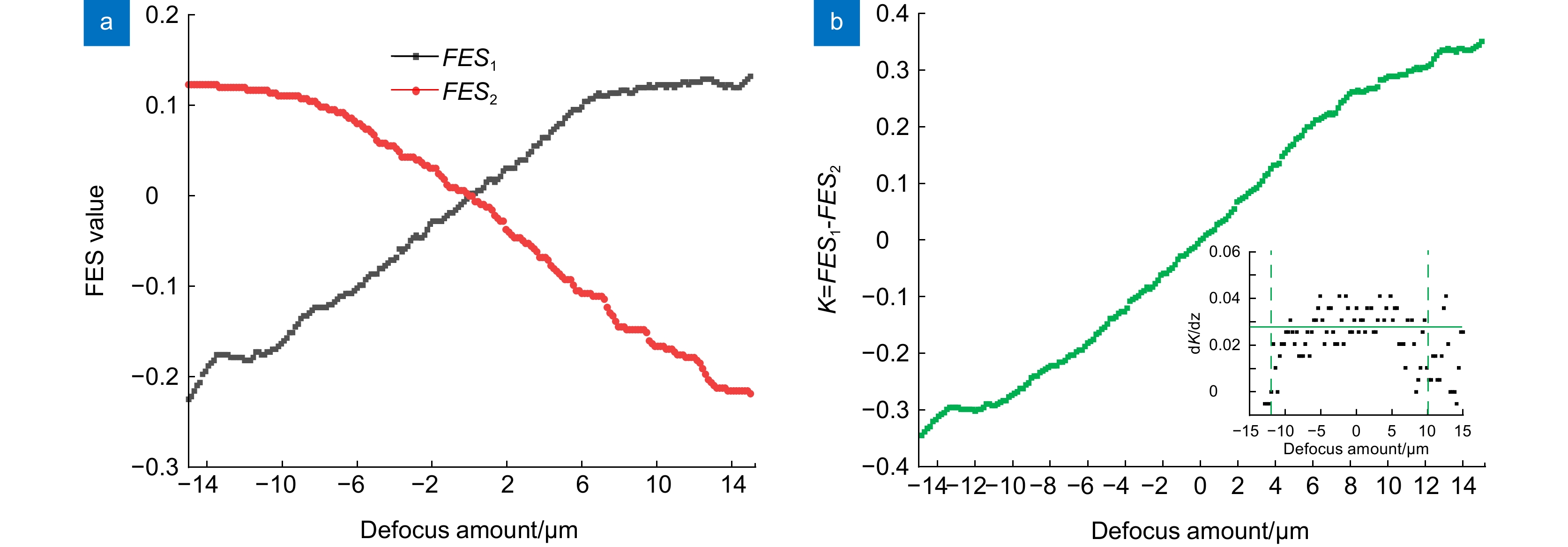
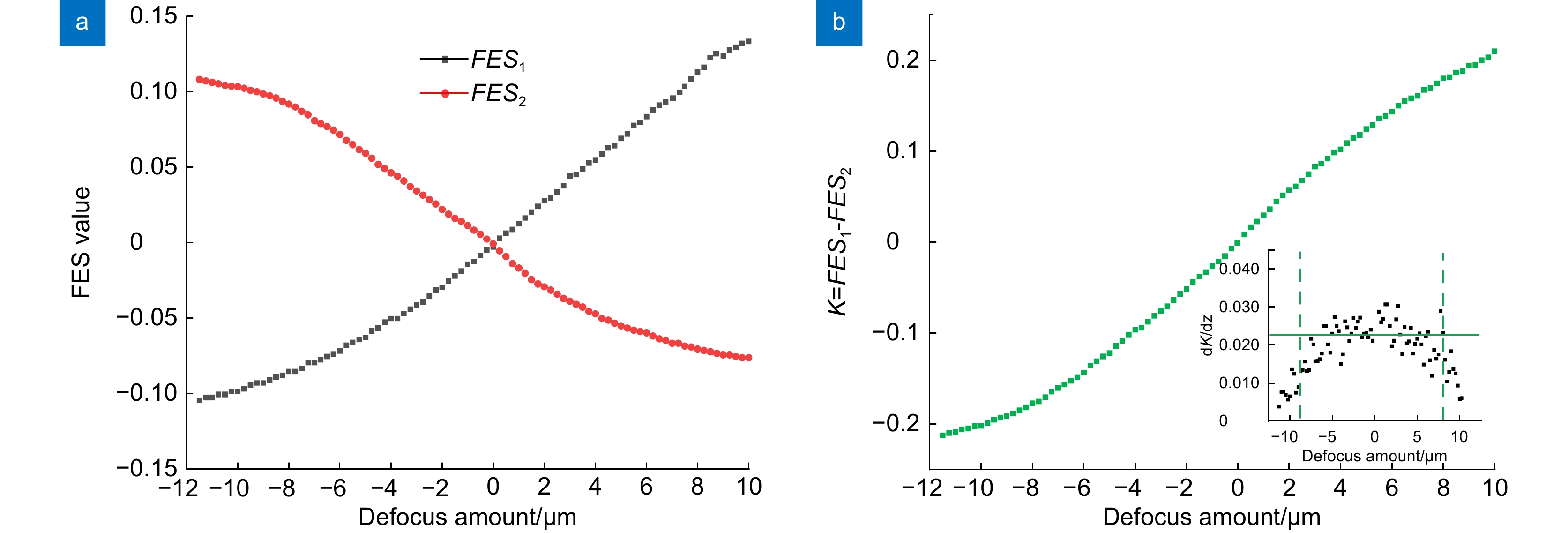
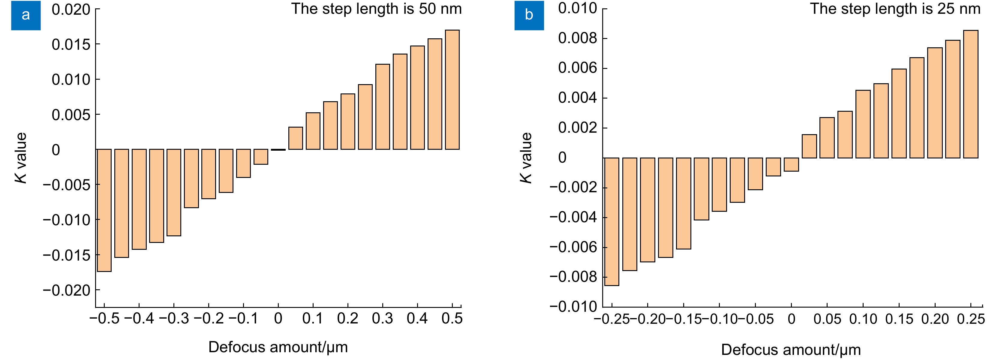
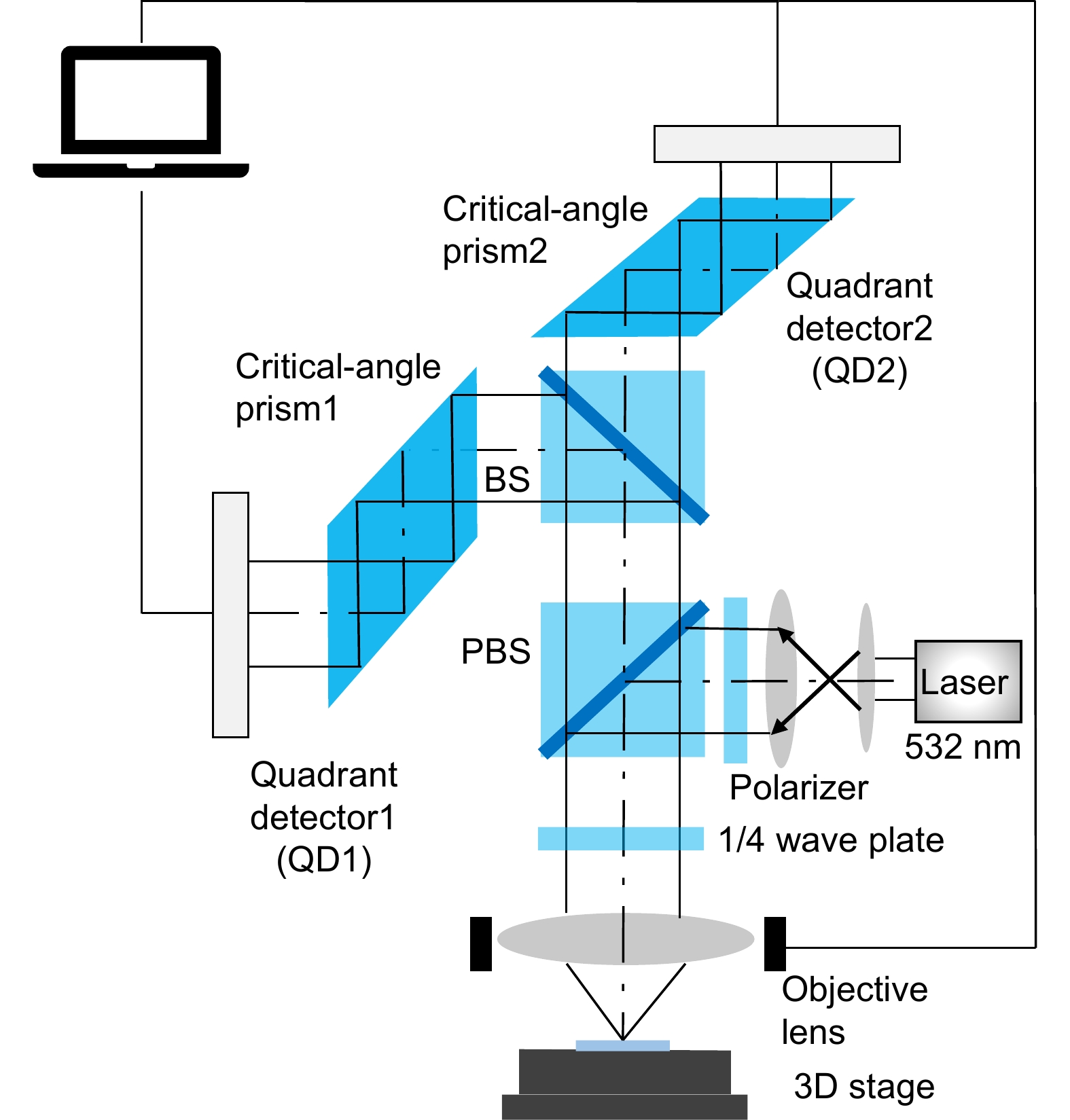
Overview: Focus detection technology utilizes precise position control and feedback systems to achieve precise control of machining, thereby achieving high-precision detection and processing of surface morphology features. With the continuous development of integrated circuits, the resolution requirements for micro/nano processing are constantly increasing. Traditional lithography techniques such as increasing the numerical aperture (NA) of the objective lens and decreasing the exposure wavelength are used to improve the system's resolution. As a result, the depth of focus is constantly decreasing, making it more difficult to focus. To ensure high-resolution and high-quality micro/nano graphic manufacturing, the substrate for micro/nano processing must be within the depth of focus range, so sub-micron level focusing private server systems must be used. Based on the characteristics of low optical energy loss, relatively simple assembly, easy debugging, and high system resolution of critical angle focusing technology, differential technology is introduced to eliminate the distortion generated by a single detector, improve the smoothness of the focusing curve, and achieve a larger range of focusing detection, reducing the focusing error affected by the unevenness of the substrate itself. This article introduces the basic principle of differential critical angle-focusing technology. The relationship between the defocus amount and defocus signal is obtained through the Fresnel formula and Newton formula. Due to the different divergence angles after defocus, the total reflection phenomenon of light is utilized. When the distance between the sample and the detector changes slightly, it will cause a change in the total reflection angle. When the beam is incident on the critical angle prism, the light intensity reflection coefficient changes with the different incident angles, resulting in an asymmetric distribution of the output light spot along both sides of the optical axis. Build a differential critical angle method focusing verification system, use the defocus signal of a single critical angle prism collected by a quadrant photodetector, and perform a differential calculation on the defocus signal received by two vertically placed quadrant photodetectors to obtain the relationship between the differential K value and the defocus amount z. The experimental results show that when using a 532 nm wavelength laser and a projection objective with a numerical aperture of 0.3, the linear range of focus detection can reach 22 μm. When using a projection objective with a numerical aperture of 0.45, the linear range of focus detection can reach 14 μm. The differential critical angle focusing method has the resolution better than 25 nm.
-

-
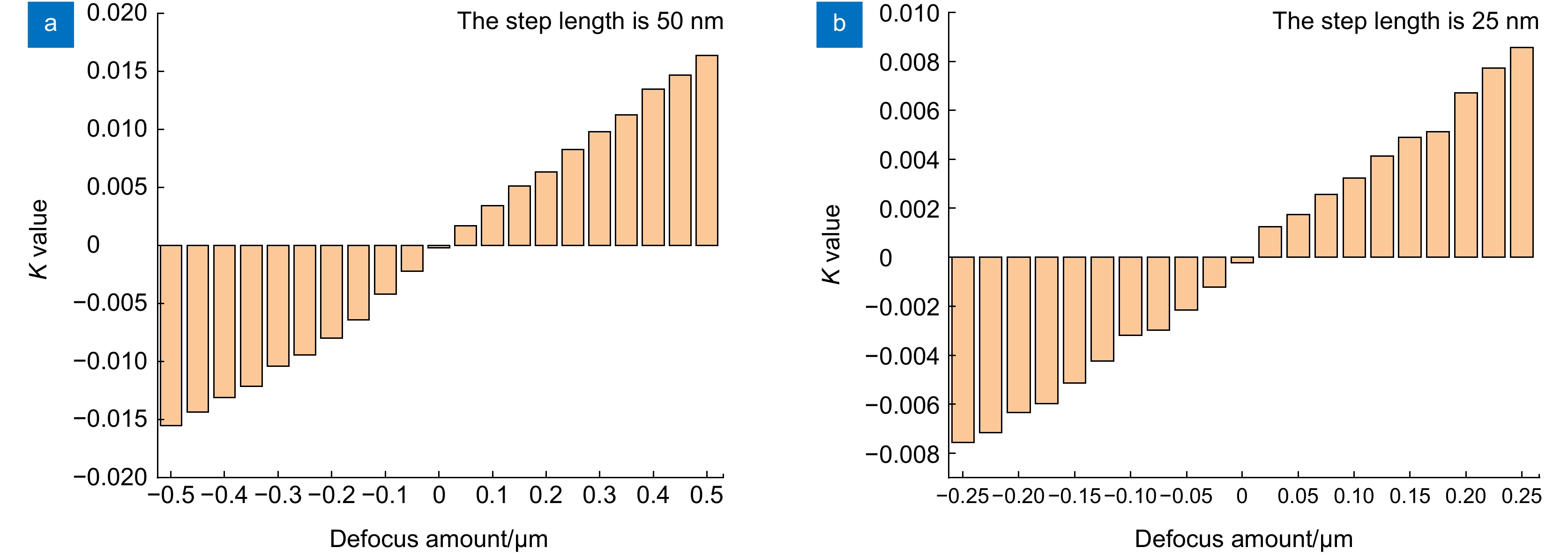
表 1 NA=0.3采用不同增量差动临界角检焦信号的输出信号结果
Table 1. NA=0.3 output signal results using different incremental critical angle focusing signals
Defocus/μm −0.5 −0.45 −0.4 −0.35 −0.3 −0.25 −0.2 K −0.01738 −0.01538 −0.01423 −0.01327 −0.01231 −0.00831 −0.00702 Defocus/μm −0.15 −0.1 −0.05 0 0.05 0.1 0.15 K −0.00615 −0.00401 −0.00214 −0.0001 0.00314 0.00522 0.00677 Defocus/μm 0.2 0.25 0.3 0.35 0.4 0.45 0.5 K 0.00791 0.00922 0.01211 0.01355 0.0147 0.01574 0.01695 Defocus/μm −0.25 −0.225 −0.2 −0.175 −0.15 −0.125 −0.1 K −0.00855 −0.00755 −0.00697 −0.00667 −0.00611 −0.00415 −0.00357 Defocus/μm −0.075 −0.05 −0.025 0 0.025 0.05 0.075 K −0.00297 −0.00214 −0.00121 −0.0009 0.00156 0.00271 0.00312 Defocus/μm 0.1 0.125 0.15 0.175 0.2 0.225 0.25 K 0.00453 0.00496 0.00597 0.00671 0.00737 0.00787 0.00854 表 2 NA=0.45采用不同增量差动临界角检焦信号的输出信号结果
Table 2. Output signal results using different incremental critical angle focusing signals (NA =0.45)
Defocus/μm −0.5 −0.45 −0.4 −0.35 −0.3 −0.25 −0.2 K −0.01551 −0.01433 −0.01311 −0.01211 −0.01042 −0.00942 −0.00798 Defocus/μm −0.15 −0.1 −0.05 0 0.05 0.1 0.15 K −0.00642 −0.00417 −0.00223 −0.00019 0.00167 0.00341 0.00512 Defocus/μm 0.2 0.25 0.3 0.35 0.4 0.45 0.5 K 0.00634 0.00825 0.00978 0.01124 0.01345 0.01467 0.01636 Defocus/μm −0.25 −0.225 −0.2 −0.175 −0.15 −0.125 −0.1 K −0.00756 −0.00715 −0.00634 −0.00597 −0.00513 −0.00423 −0.00317 Defocus/μm −0.075 −0.05 −0.025 0 0.025 0.05 0.075 K −0.00297 −0.00215 −0.00121 −0.00023 0.00124 0.00174 0.00257 Defocus/μm 0.1 0.125 0.15 0.175 0.2 0.225 0.25 K 0.00323 0.00414 0.00489 0.00512 0.00671 0.00774 0.00857 -
参考文献
[1] 梁嵘, 李达成, 曹芒, 等. 表面微观形貌测量及其参数评定的发展趋势[J]. 光学技术, 1998, (6): 66−68.
Liang R, Li D C, Cao M, et al. Measurement and characterization tendency of the surface microtopography[J]. Opt Technol, 1998, (6): 66−68.
[2] 王建. 基于偏振调制的高精度焦面检测技术研究[D]. 成都: 中国科学院大学(中国科学院光电技术研究所), 2021: 7–10.
Wang J. Study on high precision measurement technology of wafer focus based on polarization modulation[D]. Chengdu: The Institute of Optics and Electronics, The Chinese Academy of Sciences, 2021: 7–10.
[3] 孙裕文, 李世光, 宗明成. 基于空间分光的纳米级调焦调平测量技术[J]. 光学学报, 2016, 36(5): 0512002. doi: 10.3788/AOS201636.0512002
Sun Y W, Li S G, Zong M C. Nanoscale focusing and leveling measurement technology based on optical spatial split[J]. Acta Opt Sin, 2016, 36(5): 0512002. doi: 10.3788/AOS201636.0512002
[4] 金占雷, 谭九彬, 张山, 等. 离焦激光直写的线宽稳定方法[J]. 光学学报, 2008, 28(9): 1730−1734. doi: 10.3321/j.issn:0253-2239.2008.09.018
Jin Z L, Tan J B, Zhang S, et al. Research of linewidth stabilizing method during defocusing laser direct writing[J]. Acta Opt Sin, 2008, 28(9): 1730−1734. doi: 10.3321/j.issn:0253-2239.2008.09.018
[5] 张玉虎, 李亚文, 罗传文, 等. TFT光刻平面倾斜对光刻图形的影响及改善[J]. 光电工程, 2019, 46(10): 180679. doi: 10.12086/oee.2019.180679
Zhang Y H, Li Y W, Luo C W, et al. The effect of TFT lithography plane inclination on lithography pattern and improvement[J]. Opto-Electron Eng, 2019, 46(10): 180679. doi: 10.12086/oee.2019.180679
[6] 鲁倩, 任斌, 边晶莹. 四象限探测器的信号光捕获与跟踪技术研究[J]. 光电工程, 2020, 47(3): 190559. doi: 10.12086/oee.2020.190559
Lu Q, Ren B, Bian J Y. Research on acquisition and tracking technology for the four-quadrant detector[J]. Opto-Electron Eng, 2020, 47(3): 190559. doi: 10.12086/oee.2020.190559
[7] 赵圆圆, 金峰, 董贤子, 等. 飞秒激光双光子聚合三维微纳结构加工技术[J]. 光电工程, 2023, 50(3): 220048. doi: 10.12086/oee.2023.220048
Zhao Y Y, Jin F, Dong X Z, et al. Femtosecond laser two-photon polymerization three-dimensional micro-nanofabrication technology[J]. Opto-Electron Eng, 2023, 50(3): 220048. doi: 10.12086/oee.2023.220048
[8] Wittekoek S, van den Brink M A, Linders H F D, et al. Deep-UV wafer stepper with through-the-lens wafer to reticle alignment[J]. Proc SPIE, 1990, 1264: 534−547. doi: 10.1117/12.20207
[9] van der Werf J E. Optical focus and level sensor for wafer steppers[J]. J Vac Sci Technol B, 1992, 10(2): 735−740. doi: 10.1116/1.586439
[10] 冯金花, 唐燕, 谢仲业, 等. 基于差动调制度解析的同轴检焦方法[J]. 光学学报, 2021, 41(6): 0612001. doi: 10.3788/AOS202141.0612001
Feng J H, Tang Y, Xie Z Y, et al. Coaxial focusing method based on differential modulation evaluation[J]. Acta Opt Sin, 2021, 41(6): 0612001. doi: 10.3788/AOS202141.0612001
[11] 潘萍. 差动像散离焦检测技术研究[D]. 哈尔滨: 哈尔滨工业大学, 2010: 1–5.
Pan P. Study on differential astigmatism detection technology[D]. Harbin: Harbin Institute of Technology, 2010: 1–5.
[12] 梁凤超. 临界角法激光直写聚焦伺服系统静态特性研究[J]. 电光与控制, 2011, 18(5): 59−62,79. doi: 10.3969/j.issn.1671-637X.2011.05.014
Liang F C. Static characteristics of auto-focusing servo system based on critical angle method for laser direct writing[J]. Electron Opt Control, 2011, 18(5): 59−62,79. doi: 10.3969/j.issn.1671-637X.2011.05.014
[13] 郝贤鹏, 任建岳, 邹振书. 临界角法检焦系统的设计[J]. 光学 精密工程, 2009, 17(3): 537−541. doi: 10.3321/j.issn:1004-924X.2009.03.012
Hao X P, Ren J Y, Zou Z S. Design of focus error detection system based on critical angle method[J]. Opt Precis Eng, 2009, 17(3): 537−541. doi: 10.3321/j.issn:1004-924X.2009.03.012
[14] 龚健文, 王建, 刘俊伯, 等. 基于投影光刻技术的微透镜阵列加工方法[J]. 光电工程, 2023, 50(12): 230281. doi: 10.12086/oee.2023.230281
Gong J W, Wang J, Liu J B, et al. Microlens array machining method based on projection lithography[J]. Opto-Electron Eng, 2023, 50(12): 230281. doi: 10.12086/oee.2023.230281
[15] 李光, 朱江平, 陈铭勇, 等. 基于干涉的同轴检焦新方法[J]. 中国激光, 2013, 40(12): 1208005. doi: 10.3788/CJL201340.1208005
Li G, Zhu J P, Chen M Y, et al. Novel coaxial focusing method based on interference[J]. Chin J Lasers, 2013, 40(12): 1208005. doi: 10.3788/CJL201340.1208005
[16] Liu Y, Luo N N, Chen Z R, et al. Research on high precision and large range automatic focusing method for digital lithography[J]. Proc SPIE, 2024, 13104: 131041N. doi: 10.1117/12.3022592
[17] 李旺, 张文涛, 杜浩, 等. 扫描白光干涉技术在硅片检焦过程中的应用[J]. 现代电子技术, 2023, 46(15): 140−146. doi: 10.16652/j.issn.1004-373x.2023.15.025
Li W, Zhang W T, Du H, et al. Application of scanning white light interferometry in process of silicon wafer focusing[J]. Modern Electron Tech, 2023, 46(15): 140−146. doi: 10.16652/j.issn.1004-373x.2023.15.025
[18] Du J L, Yan W, Liu L W, et al. Focal surface detection of high numerical aperture objective lens based on differential astigmatic method[J]. IEEE Photonics J, 2021, 13(4): 5800208. doi: 10.1109/JPHOT.2021.3097086
[19] 吴玉年. 临界角法在聚焦伺服系统中的应用[D]. 长春: 长春理工大学, 2001.
Wu Y N. Application of critical-angle method on the focus servo[D]. Changchun: Changchun University of Science and Technology, 2001.
[20] 陈海清, 常洋燕, 阮玉. 关于临界角法菲涅耳公式简化理论处理的新方法[J]. 光子学报, 1995, 24(6): 551−554.
Chen H Q, Chang Y Y, Ruan Y. The new method of a simplified processes F Fresnel formula for the method of critical angle[J]. Acta Photon Sin, 1995, 24(6): 551−554.
[21] 文江华, 赵创社, 姜粉娥, 等. 基于压电陶瓷的快速反射镜驱动与控制研究[J]. 兵工自动化, 2015, 34(8): 59−64. doi: 10.7690/bgzdh.2015.08.015
Wen J H, Zhao C S, Jiang F E, et al. Study of driving and controlling with fast steering mirror based on PZT[J]. Ordnance Ind Autom, 2015, 34(8): 59−64. doi: 10.7690/bgzdh.2015.08.015
[22] 杨聚圃, 杜佳林, 李凡星, 等. 基于深度学习的数字光刻自动检焦方法[J]. 光子学报, 2022, 51(6): 0611002. doi: 10.3788/gzxb20225106.0611002
Yang J P, Du J L, Li F X, et al. Deep learning based method for automatic focus detection in digital lithography[J]. Acta Photon Sin, 2022, 51(6): 0611002. doi: 10.3788/gzxb20225106.0611002
-
访问统计


 E-mail Alert
 RSS
RSS

 下载:
下载:


