
 E-mail Alert
 RSS
RSS
-
摘要
在现有的激光雷达技术中,频率调制连续波体制的激光雷达相比于传统的飞行时间激光雷达具有分辨力高、测量准确度高、设备轻巧、功耗低等优势;得益于使用连续光信号进行测量,调频连续波激光雷达还具有高灵敏度、信息量丰富、处理解调容易等特有的性能。对高分辨力、高准确度的探测需求而言具有很强的竞争力,并具有非常好的集成化、小型化、低能耗的潜力。本文介绍了调频连续波激光雷达的基本工作原理和重要参数,根据实现频率调制连续波的激光光源方案,分类介绍了近十几年来调频连续波雷达的研究进展,并探讨了各种方案的特点。
Abstract
Among the existing LiDAR technologies, the LiDAR with frequency modulation continuous wave (FMCW) format has the advantages of high resolution, high measurement accuracy, light weight, low power consumption compared with the conventional time-of-flight LiDAR. Benefitting from adopting continuous lightwave for measurement, the FMCW LiDAR also has unique performances such as high sensitivity, rich information, and easy processing and demodulation. It is highly competitive for high-resolution, high-accuracy detection needs, and has the potential for very good integration, miniaturization, and low energy consumption. This paper introduces the basic principles of different LiDAR systems, especially focusing on the important parameters of FMCW LiDAR, and classifies the research work of FMCW LiDAR in the past ten years into different types based on the light source scheme, and discusses the features of various schemes.
-
Key words:
- LiDAR /
- frequency modulation /
- resolution /
- coherent detection
-
Overview

Overview: LiDAR (Laser detection and ranging) is an active remote sensing technology that uses laser for imaging, detecting and ranging. It has the advantages of high resolution, high precision, light weight and strong anti-interference. Following the invention of the laser in 1960, Radar's working bands and techniques were quickly convert by researchers from the microwave band to the optical band. Compared with the traditional microwave radar technology, the LiDAR works in a shorter wavelength band, which makes the laser beam can achieve smaller divergence angle and better directionality. As LiDAR working in the optical band, the distance resolution and angular resolution that can be achieved during detection are greatly improved. LiDAR detection can obtain complex information such as target distance, velocity, reflectivity, etc. The acquired 3D point cloud data is usually used to generate high-resolution 3D maps or 3D models, and is widely used in surveying, topography, forestry, areas of atmospheric physics, laser guidance, aerospace, deep space exploration and unmanned driving.
At present, the detection mechanism of LiDAR is mainly divided into two types, non-coherent detection and coherent detection. Non-coherent detection is also called direct detection since it directly detects the change of the amplitude of the reflected light signal. It is widely used in time-of-flight (TOF) LiDAR or amplitude-modulated continuous-wave LiDAR. Coherent detection uses heterodyne detection to detect by measuring the frequency or phase difference between the echo signal and the local oscillator signal. The current mainstream coherent detection LiDARs include frequency modulated continuous wave (FMCW) LiDAR and Doppler speed LiDAR. The heterodyne detection method has higher sensitivity than the direct detection method, which makes the coherent detection type LiDAR can work at a lower transmission power.
In view of the advantages of LiDAR, especially the coherent detection FMCW LiDAR, this paper will introduce the basic working principle of FMCW LiDAR and the recent developments. The second part introduces the working principle of FMCW LiDAR and the relationship between the basic performance of FMCW LiDAR and the parameters of the transmitting system. The third part and the fourth part introduce the generation of FMCW light by different modulation methods in the past decade and discuss the characteristics of various schemes. Methods and experiments of cavity tuning, current injection tuning and external modulation are briefly present in these two parts as well as the technique and algorithm of synthesis aperture. Finally, we compared and summarized the FMCW LiDAR systems mentioned in this review.
-

-
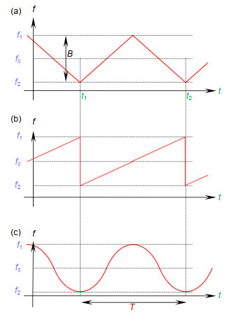
图 1 FMCW激光雷达光源的频率调制形式,显示了光载波频率随时间的变化关系。(a)三角波形式调频连续波信号时频图;(b)锯齿波形式调频连续波信号时频图;(c)正弦波形式调频连续波信号时频图
Figure 1. Frequency modulation pattern of the FMCW lidar source, representing the relationship between the frequency of optical carrier wave and the time. (a) Time frequency relationship of FMCW with the triangular modulation; (b) Time frequency relationship of FMCW with the sawtooth modulation; (c) Time frequency relationship of FMCW with the sine modulation
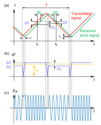
图 2 (a) 三角波形式频率调制下发射信号与接收回波信号的时频域关系示意图;(b)经相干检测所得到拍信号的时频关系图;(c)接收端拍频电信号的时域波形[10]
Figure 2. (a) Time frequency domain diagram of transmitted signal and received echo signal under the trianglar modulation; (b) Time frequency domain diagram of the beat signal after coherent detection; (c) Time domain waveform of the received beat signal[10]
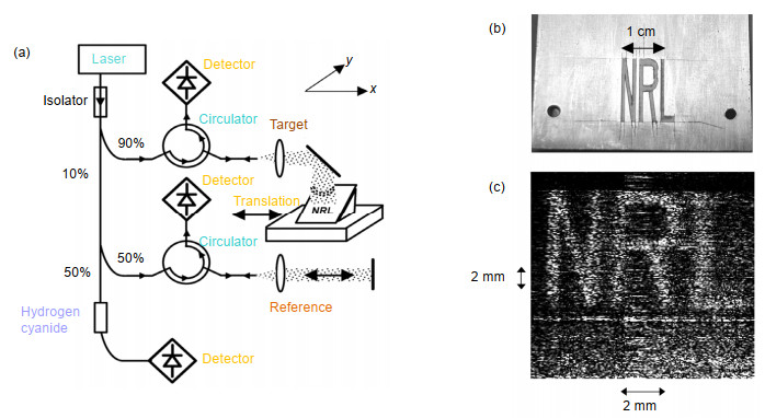
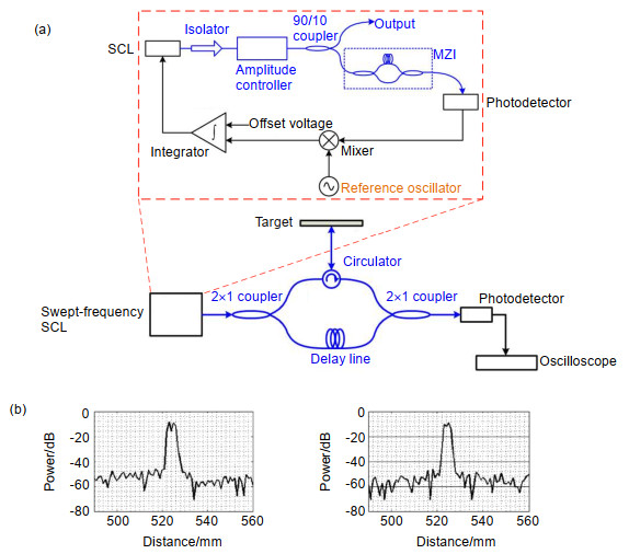
图 5 (a) 用于产生宽带线性调频光的光电反馈环路与测量装置示意图;(b)使用本扫频光源的距离测量结果:待测目标是折射率为1.5的亚克力板,厚度分别为2.25 mm和1.49 mm[20]
Figure 5. (a) Schematic of the ranging experiment with a linearly chirped optical source based on optoelectronic feedback loop; (b) Range resolution measurements using the swept-frequency SCL. The target was an acrylic sheet of refractive index 1.5 and thickness 2.25 mm and 1.49 mm[20]
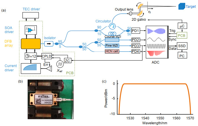
图 6 (a) 雷达扫描系统示意图, 其中ISO:光隔离器,MZI:马赫增德干涉仪,CPLD:复杂编程逻辑设备,μC:微控制器,SSD:固态存储器;(b) DFB阵列模块;(c) DFB阵列的输出光谱强度平坦[22]
Figure 6. (a) Scanning system layout, ISO: Optical isolator, MZI: Mach-Zehnder interferometers, CPLD: complex programmable logic device, µC: Teensy microcontroller, SSD: solid-state hard drive; (b) DFB array module; (c) Normalized output power over all elements[22]
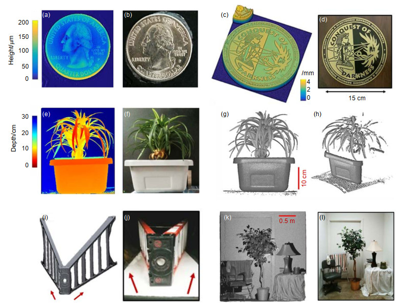
图 7 景深从毫米量级到米量级的三维成像结果。(a)位于25 cm处的25美分表面形貌成像结果;(b) 25美分的实物照片(400像素×420像素);(c)位于1.1 m处直径15 cm的奖章表面成像结果;(d) 15 cm直径奖章的实物照片(700像素×740像素);(e) 2.5 m处的物体深度结果图;(f) 2.5 m处盆栽的照片(408像素×490像素);(g)盆栽的反射率分布图;(h)盆栽的反射率分布侧视图;(i) 2.5 m远处放置的6层梯的三维成像图;(j) 6层梯照片(408像素×370像素);(k)放置了不同物体的房间的三维点云图;(l)放置了多种物体的房间照片(884像素×900像素)[22]
Figure 7. 3D images over depths ranging from less than a millimeter to meters. (a) Surface map of a (b) quarter at 25 cm (400 pixels×420 pixels); (c) Surface map of a (d) 15 cm diameter medallion at 1.1 m (700 pixels×740 pixels); (e) Volume depth map of a (f) potted plant placed at 2.5 m (408 pixels×490 pixels). Volume shown = 33.5l cm×30d cm×40h cm; (g) Reflectivity profile of the plant with a (h) rotated view; (i) 3D mesh of a (j) six-foot ladder starting at 2.5 m (408 pixels×370 pixels); (k) 3D point cloud of a (l) room with a variety of objects (884 pixels×900 pixels)[22].
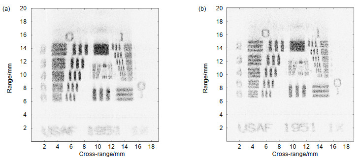

图 12 (a) 宽带调频光源原理示意图;(b)、(c)、(d)分别为A, B, C点光脉冲序列的时间-强度演变示意图;(e)、(f)分别为B和C点光脉冲序列的时间频率演变示意图[38]
Figure 12. (a) Schematic for the generation of the chirped light; (b), (c), (d) Time-intensity evolution diagrams of the pulse sequence for A, B, C; (e), (f) Time-frequency evolution diagrams of the pulse sequence for B, C [38]
表 1 9种FMCW激光雷达光源参数对比
Table 1. Specification comparison of mentioned FMCW LiDAR source
2002[16] 2005[19] 2009[20] 2018[22] 2016[24] 2012[27] 2008[32] 2018[33] 2018[38] 光源类型 内调制 内调制 内调制 内调制 内调制 内调制 外调制 外调制 外调制 调制方式 腔长调谐 腔长调谐 电流注入 电流注入 电流注入 混合调谐 电光调制 电光调制 电光调制 频率调谐范围 1.25 THz 3.73 THz 100 GHz 5.56 THz 122 GHz 3 THz 600 MHz 6 GHz 200 GHz 理论距离分辨力 120 μm 40 μm 1.5 mm 27 μm 2.45 mm 49.8 μm 25 cm 2.5 cm 750 μm 光源线宽* --- 100 kHz 1 MHz 3 MHz --- --- 10 kHz 13.9 kHz 50 kHz 相干长度* --- 1 km 100 m 32 m --- --- 10 km 7 km 2 km 重复周期 1 s 0.36 s 1 ms 3 ms 5.6 μs 600 ms 3.3 ms 60 μs 5.5 μs 发射功率 5 mW 6.3 mW 40 mW 12.7 mW 10 mW 200 mW --- 15 W 1 mW 调谐速率 1.25 GHz/ms 10.5 GHz/ms 100 GHz/ms 1.8 THz/ms 44 THz/ms 5 GHz/ms 182 MHz/ms 100 GHz/ms 36.4 THz/ms *静态工作时光源线宽测量值与由线宽计算得到相干长度  下载: 导出CSV
-
参考文献
[1] Swatantran A, Tang H, Barrett T, et al. Rapid, high-resolution forest structure and terrain mapping over large areas using single photon lidar[J]. Scientific Reports, 2016, 6(1): 28277. doi: 10.1038/srep28277
[2] Jaboyedoff M, Oppikofer T, Abellán A, et al. Use of LIDAR in landslide investigations: a review[J]. Natural Hazards, 2012, 61(1): 5–28. doi: 10.1007/s11069-010-9634-2
[3] Lim K, Treitz P, Wulder M, et al. LiDAR remote sensing of forest structure[J]. Progress in Physical Geography: Earth and Environment, 2003, 27(1): 88–106. doi: 10.1191/0309133303pp360ra
[4] Goyer G G, Watson R. The laser and its application to meteorology[J]. Bulletin of the American Meteorological Society, 1963, 44(9): 564–570. doi: 10.1175/1520-0477-44.9.564
[5] Gschwendtner A B, Keicher W E. Development of coherent laser radar at Lincoln Laboratory[J]. Lincoln Laboratory Journal, 2000, 12(2): 383–396. http://www.wanfangdata.com.cn/details/detail.do?_type=perio&id=h0mYEcbt1nFPrFS1PS5jzfkdkVBOUriFh1zUlKq5630=
[6] Pfrunder A, Borges P V K, Romero A R, et al. Real-time autonomous ground vehicle navigation in heterogeneous environments using a 3D LiDAR[C]//Proceedings of 2017 IEEE/RSJ International Conference on Intelligent Robots and Systems, Vancouver, BC, Canada, 2017: 2601–2608.
[7] Cracknell A P, Hayes L. Introduction to Remote Sensing[M]. 2nd ed. Boca Raton: CRC Press, 2007.
[8] Martin A, Dodane D, Leviandier L, et al. Photonic integrated circuit-based FMCW coherent LiDAR[J]. Journal of Lightwave Technology, 2018, 36(19): 4640–4645. doi: 10.1109/JLT.2018.2840223
[9] Zheng J. Analysis of optical frequency-modulated continuous-wave interference[J]. Applied Optics, 2004, 43(21): 4189–4198. doi: 10.1364/AO.43.004189
[10] Wolff C. Frequency-modulated continuous-wave radar (FMCW Radar)[EB/OL]. (2016-12-01) [2019-01-08]. http://demonstra-tions.wolfram.com/FrequencyModulatedContinuousWaveFMCWRadar/.
[11] Bissonnette L R. Multiple-scattering lidar equation[J]. Applied Optics, 1996, 35(33): 6449–6465. doi: 10.1364/AO.35.006449
[12] Burdic W S. Radar Signal Analysis[M]. Englewood Cliffs: Prentice-Hall, 1968.
[13] Lichti D D, Jamtsho S. Angular resolution of terrestrial laser scanners[J]. The Photogrammetric Record, 2006, 21(114): 141–160. doi: 10.1111/phor.2006.21.issue-114
[14] Curlander J C, McDonough R N. Synthetic Aperture Radar[M]. New York, NY, USA: John Wiley & Sons, 1991.
[15] Ito F, Fan X Y, Koshikiya Y. Long-range coherent OFDR with light source phase noise compensation[J]. Journal of Lightwave Technology, 2012, 30(8): 1015–1024. doi: 10.1109/JLT.2011.2167598
[16] Bashkansky M, Lucke R L, Funk E, et al. Two-dimensional synthetic aperture imaging in the optical domain[J]. Optics Letters, 2002, 27(22): 1983–1985. doi: 10.1364/OL.27.001983
[17] Skolnik M I. Radar Handbook[M]. New York NY, USA: McGraw-Hill, 1970.
[18] Buell W, Marechal N, Buck J, et al. Demonstration of synthetic aperture imaging ladar[J]. Proceedings of SPIE, 2005, 5791: 152–166. doi: 10.1117/12.609682
[19] Beck S M, Buck J R, Buell W F, et al. Synthetic-aperture imaging laser radar: laboratory demonstration and signal processing[J]. Applied Optics, 2005, 44(35): 7621–7629. doi: 10.1364/AO.44.007621
[20] Satyan N, Vasilyev A, Rakuljic G, et al. Precise control of broadband frequency chirps using optoelectronic feedback[J]. Optics Express, 2009, 17(18): 15991–15999. doi: 10.1364/OE.17.015991
[21] Satyan N, Vasilyev A, Rakuljic G, et al. Phase-locking and coherent power combining of broadband linearly chirped optical waves[J]. Optics Express, 2012, 20(23): 25213–25227. doi: 10.1364/OE.20.025213
[22] DiLazaro T, Nehmetallah G. Large-volume, low-cost, high-precision FMCW tomography using stitched DFBs[J]. Optics Express, 2018, 26(3): 2891–2904. doi: 10.1364/OE.26.002891
[23] DiLazaro T, Nehmetallah G. Large depth high-precision FMCW tomography using a distributed feedback laser array[J].Proceedings of SPIE, 2018, 10539: 1053906.
[24] Behroozpour B, Sandborn P A M, Quack N, et al. 11.8 Chip-scale electro-optical 3D FMCW lidar with 8μm ranging precision[C]//Proceedings of 2016 IEEE International Solid-State Circuits Conference, San Francisco, CA, USA, 2016: 214–216.
[25] Poulton C V, Yaacobi A, Cole D B, et al. Coherent solid-state LIDAR with silicon photonic optical phased arrays[J]. Optics Letters, 2017, 42(20): 4091–4094. doi: 10.1364/OL.42.004091
[26] Roos P A, Reibel R R, Berg T, et al. Ultrabroadband optical chirp linearization for precision metrology applications[J]. Optics Letters, 2009, 34(23): 3692–3694. doi: 10.1364/OL.34.003692
[27] Crouch S, Barber Z W. Laboratory demonstrations of interferometric and spotlight synthetic aperture ladar techniques[J]. Optics Express, 2012, 20(22): 24237–24246. doi: 10.1364/OE.20.024237
[28] Carrara W, Majewski R M, Goodman R S. Spotlight Synthetic Aperture Radar: Signal Processing Algorithms[M]. Boston: Artech House, 1995.
[29] Jakowatz Jr C V, Wahl D E, Eichel P H, et al. Spotlight-Mode Synthetic Aperture Radar: A Signal Processing Approach[M]. Boston, MA, USA: Springer, 1996.
[30] Wahl D E, Eichel P H, Ghiglia D C, et al. Phase gradient autofocus-a robust tool for high resolution SAR phase correction[J]. IEEE Transactions on Aerospace and Electronic Systems, 1994, 30(3): 827–835. doi: 10.1109/7.303752
[31] Yocky D, Wahl D, Jakowatz Jr C. Spotlight-mode SAR image formation utilizing the chirp Z-transform in two dimensions[C]//Proceedings of 2006 IEEE International Symposium on Geoscience and Remote Sensing, Denver, CO, USA, 2006: 4180–4182.
[32] Pierrottet D, Amzajerdian F, Petway L, et al. Linear FMCW laser radar for precision range and vector velocity measurements[J]. MRS Online Proceedings Library Archive, 2008, 1076: 1076–K04–06. doi: 10.1557/PROC-1076-K04-06
[33] Wang N, Wang R, Mo D, et al. Inverse synthetic aperture LADAR demonstration: system structure, imaging processing, and experiment result[J]. Applied Optics, 2018, 57(2): 230–236. doi: 10.1364/AO.57.000230
[34] Lyu Y K, Yang T X, Lu Z Y, et al. External modulation method for generating accurate linear optical FMCW[J]. IEEE Photonics Technology Letters, 2017, 29(18): 1560–1563. doi: 10.1109/LPT.2017.2736561
[35] Li G Z, Wang R, Song Z Q, et al. Linear frequency-modulated continuous-wave ladar system for synthetic aperture imaging[J]. Applied Optics, 2017, 56(12): 3257–3262. doi: 10.1364/AO.56.003257
[36] Chen V C, Ling H. Time-frequency Transforms for Radar Imaging and Signal Analysis[M]. Boston, MA, USA: Artech House, 2002.
[37] Shimizu K, Horiguchi T, Koyamada Y. Technique for translating light-wave frequency by using an optical ring circuit containing a frequency shifter[J]. Optics Letters, 1992, 17(18): 1307–1309. doi: 10.1364/OL.17.001307
[38] Lu Z Y, Yang T X, Li Z Y, et al. Broadband linearly chirped light source with narrow linewidth based on external modulation[J]. Optics Letters, 2018, 43(17): 4144–4147. doi: 10.1364/OL.43.004144
[39] Yariv A, Yeh P. Photonics: Optical Electronics in Modern Communications[M]. 6th ed. New York, NY, USA: Oxford University Press, 2006.
-
访问统计
 点击扫一扫
点击扫一扫
图(12)
表(1)
计量
- 文章访问数:
- PDF下载数:
- 施引文献: 0


