
 E-mail Alert
 RSS
RSS
Optical system design of wedge beam splitter splitting mid-wave infrared Fizeau interferometer
-
摘要:
针对中波红外波段胶合立方型分束镜分光局限的问题,本文提出基于光楔分光的中波红外Fizeau干涉仪光学设计方案。在3.39 μm工作波长下,为降低干涉系统回程误差,提升测量准确度,采用了两次反射折叠准直光路结构,既保证良好的准直波前,同时优化设计光楔兼顾干涉成像波前。设计采用ZnSe、CaF2材料,干涉仪准直镜为单片平凸非球面结构,成像镜由双分离式球面镜构成,经蒙特卡罗模拟公差分析,准直镜0.1°视场内准直波前PV优于
λ /4,归一化出射孔径内角像差优于3.01×10−5 rad;干涉成像光路归一化视场成像波前PV优于λ /5,在25 lp/mm处MTF值优于0.38,干涉系统最大成像畸变优于0.11%;在标准面0°视场放置,被测表面倾斜0.05°内干涉系统回程误差小于λ /50。基于光楔分光的中波红外Fizeau干涉仪为中波红外干涉仪光学系统设计提供了新的思路。Abstract:To solve the problem of beam splitting limitation of cemented cubic beam splitters in the mid-wave infrared band, the optical design scheme of mid-wave infrared Fizeau interferometers based on wedge splitting is proposed. At the working wavelength of 3.39 μm, to reduce the return error of the interference system and improve the measurement accuracy, a two-reflection folding collimating optical path structure is adopted, which not only ensures a good collimating wavefront, but also optimizes the design of the optical wedge to take into account the wavefront quality of the interference imaging. ZnSe and CaF2 materials are used, the collimator of the interferometer is a single plano-convex aspheric structure, and the imaging lens is composed of two separate spherical mirrors. Through the Montecarlo simulation tolerance analysis, the collimator wavefront PV of the collimator within 0.1° field of view is better than
λ/ 4. The normalized field of view imaging wavefront PV of the interferometric optical path is better thanλ/ 5; The interferometric system return error is smaller thanλ /50 at 0° field of view placed on the standard surface and the surface under test is tilted within 0.05°. -
Overview: The mid-wave infrared interferometer is an important precision instrument for measuring the refractive index uniformity of infrared materials, wave aberration of infrared optical systems, and spherical surface shape. Its optical system design has certain difficulties. In the spectroscopy scheme, it is difficult to realize spectroscopy by using the glued cubic beam splitter, and it is easy to introduce aberration mainly by image dispersion in the interferometric spectroscopy system by using the flat beam splitter. To investigate the design difficulties of the optical system of the mid-wave infrared Fizeau interferometer and the limitations of the spectroscopic scheme, this paper proposes the design of the mid-wave infrared Fizeau interferometer based on optical wedge spectroscopy. The use of optical wedge spectroscopy can effectively correct the image scattering aberration introduced by flat beam splitter spectroscopy in the interferometric imaging wavefront, which can improve the quality of the interferometric imaging wavefront, reduce the return error of the interferometric system, and improve the accuracy of measurement. This paper focuses on the effect of the collimator, wedge tilt angle, wedge angle, and other parameters on the optimized wavefront of the interference optical system. According to the above analysis, the optical system design of the mid-wave infrared Fizeau interferometer was completed. The twice reflective folding collimated optical path is used to ensure a well collimated wavefront of the interferometer by controlling the angular aberration design of the single plano-convex aspherical collimator, and the imaging aberration and normalized field-of-view imaging wavefront of the interferometric optical path are strictly controlled to reduce the return error of the interferometric system and improve the interferometric accuracy. At the working wavelength of 3.39 μm, ZnSe, and CaF2 materials are used, the collimator of the interferometer is a single plano-convex aspheric structure, and the imaging mirror is composed of two separate spherical mirrors. Through the Montecarlo simulation tolerance analysis, the collimation wavefront PV of the collimator within 0.1° field of view is better than λ⁄4, and the normalized angular aberration of the exit aperture is better than 3.01×10⁻⁵ rad. The normalized field of view imaging wavefront PV of the interferometric optical path is better than λ/5, the MTF value is better than 0.38 at 25 lp/mm, and the maximum imaging distortion of the interferometric system is smaller than 0.1%. The interferometric system return error is smaller than λ/50 at 0° field of view placed on the standard surface and the surface under test is tilted within 0.05°. The mid-wave infrared Fizeau interferometer based on optical wedge spectroscopy provides a new idea for the design of optical systems for mid-wave infrared interferometers.
-

-
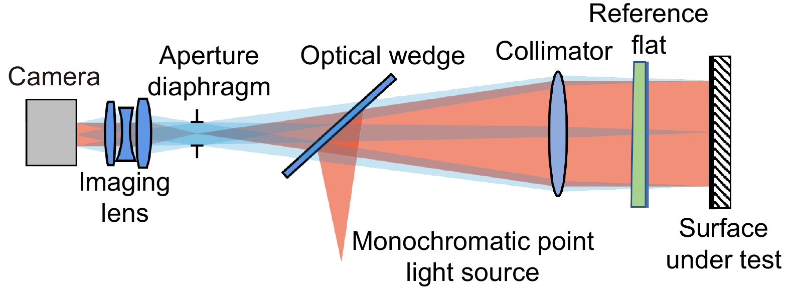
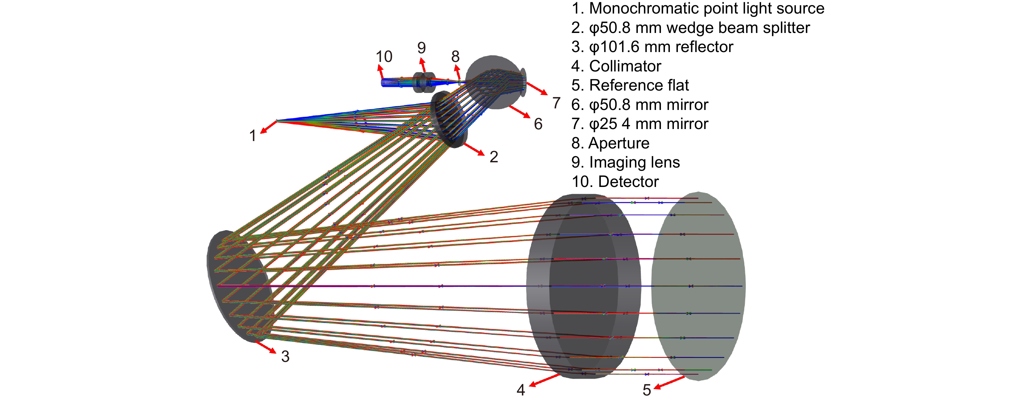
图 1 光楔分光中波红外Fizeau干涉仪原理图
Figure 1. Schematic design of the wedge splitting mediumwave infrared Fizeau interferometer
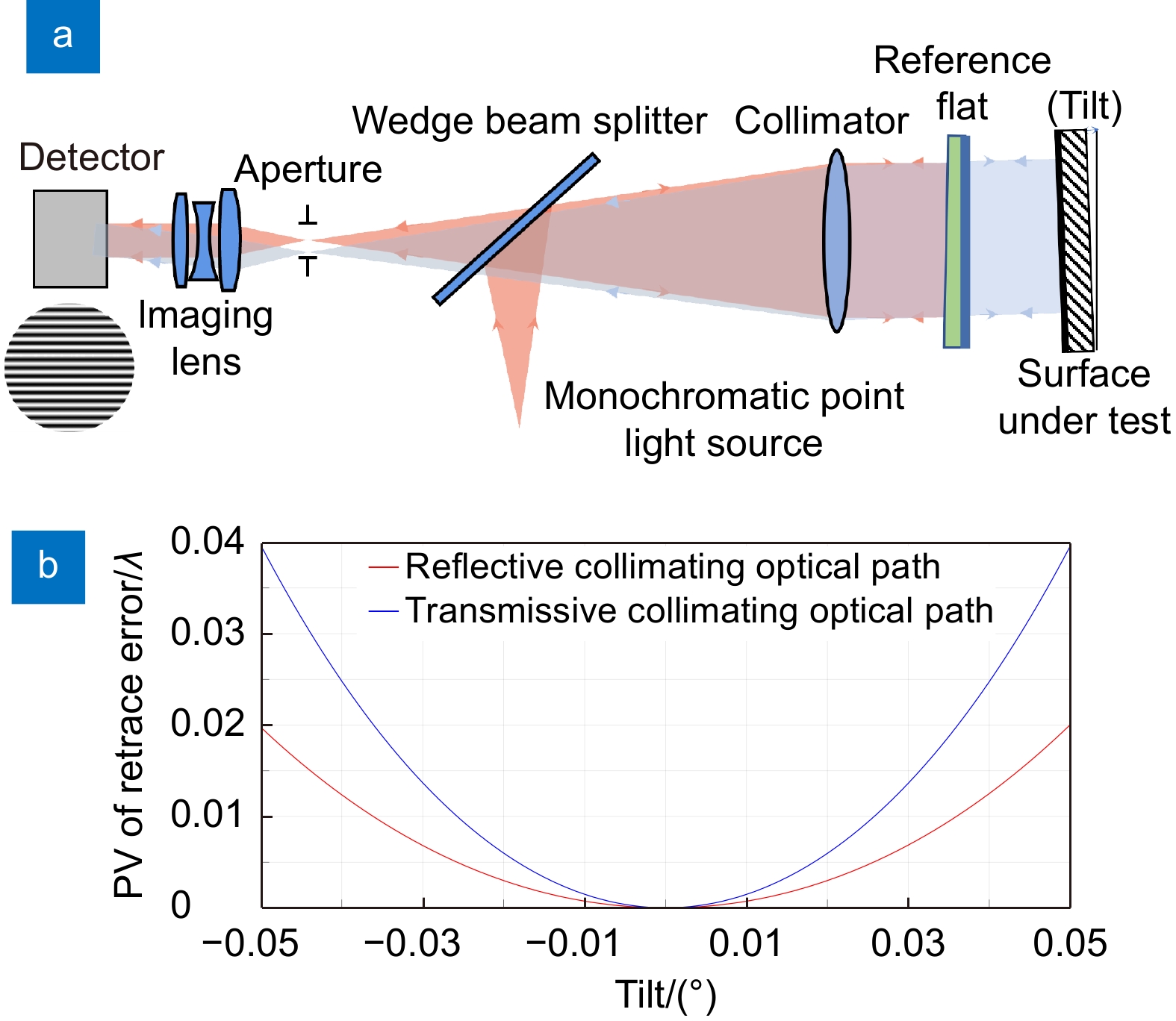
图 2 干涉系统回程误差。(a) 反射式准直出光干涉系统回程误差示意图;(b) 反射式、透射式准直出光干涉系统回程误差
Figure 2. Return error of the interference system. (a) Return error diagram of the reflective collimating optical interference system; (b) Return error of the reflective and transmissive collimating optical path interference system
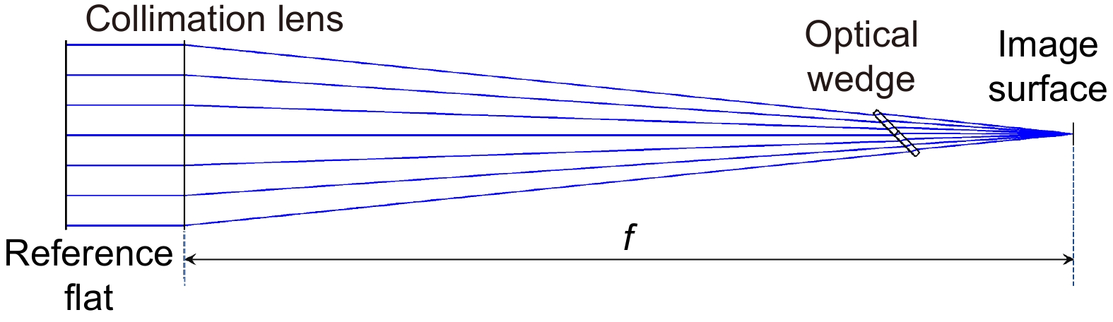
图 3 光楔波前仿真光路示意图
Figure 3. Schematic diagram of the optical path of the wedge beam splitter wavefront simulation
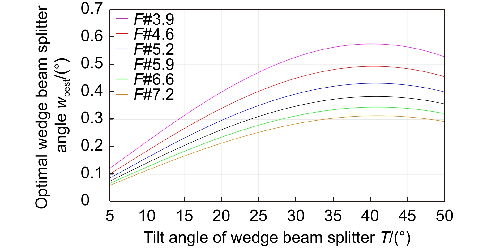
图 4 不同准直镜F#、光楔倾斜角T下光楔最优楔角
${w_{{\rm{best}}}}$ 曲线Figure 4. Optimal wedge beam splitter angle
${w_{{\rm{best}}}}$ curves for different collimator F# and tilt angles of the wedge beam splitter T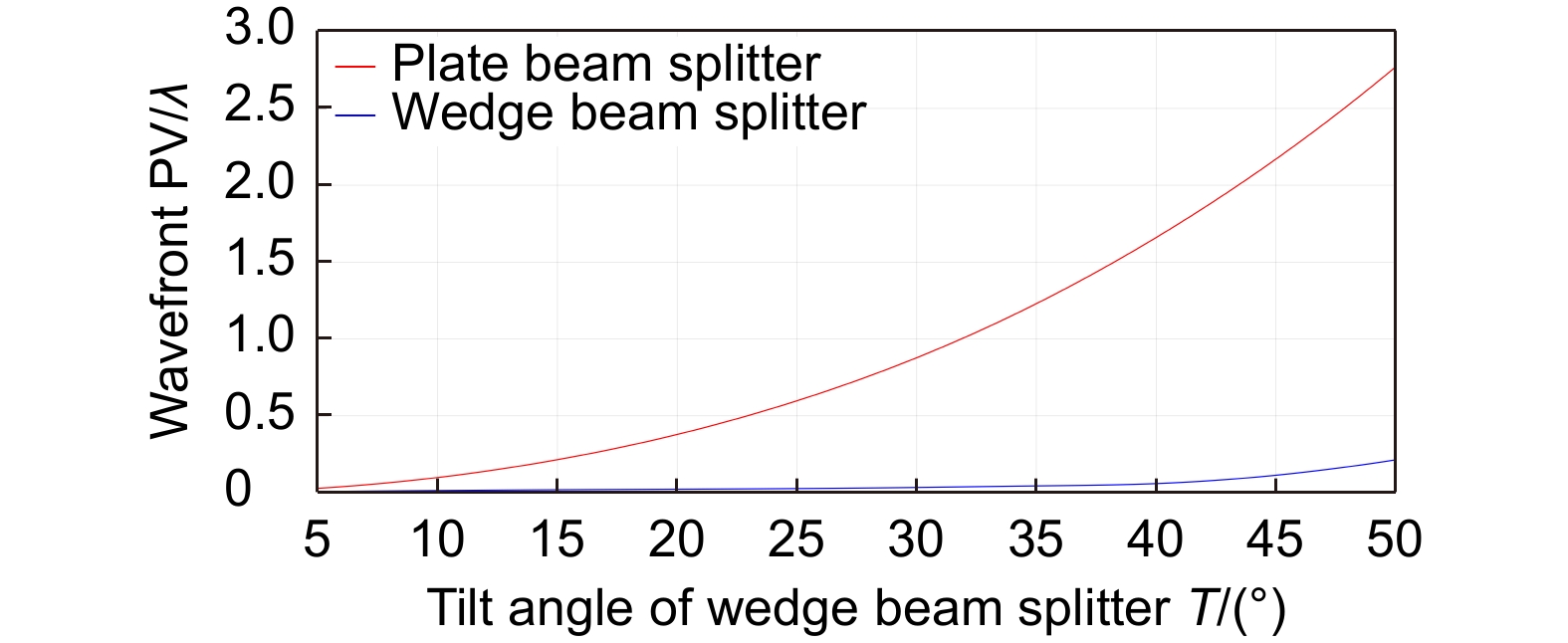
图 5 平板型分束镜、光楔在不同倾斜角T下分光干涉系统波前PV曲线
Figure 5. Wavefront PV curve of the plate beam splitter and wedge beam splitter interference system at different tilt angles of the beam splitter T
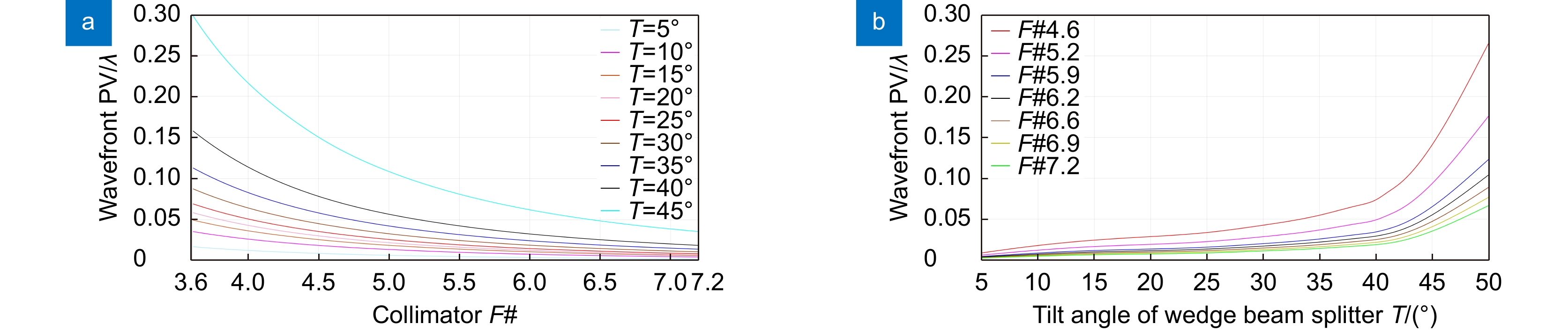
图 6 光楔分光干涉系统波前PV曲线。(a)光楔分光干涉系统波前PV与准直镜F#关系;(b) 光楔分光干涉系统波前PV与光楔倾斜角T关系
Figure 6. Wavefront PV curve of the wedge beam splitter interference system. (a) Relationship between wavefront PV of wedge beam splitter interferometric system and collimator F#; (b) Relationship between wavefront PV of wedge beam splitter interferometric system and tilt angle of wedge beam splitter T
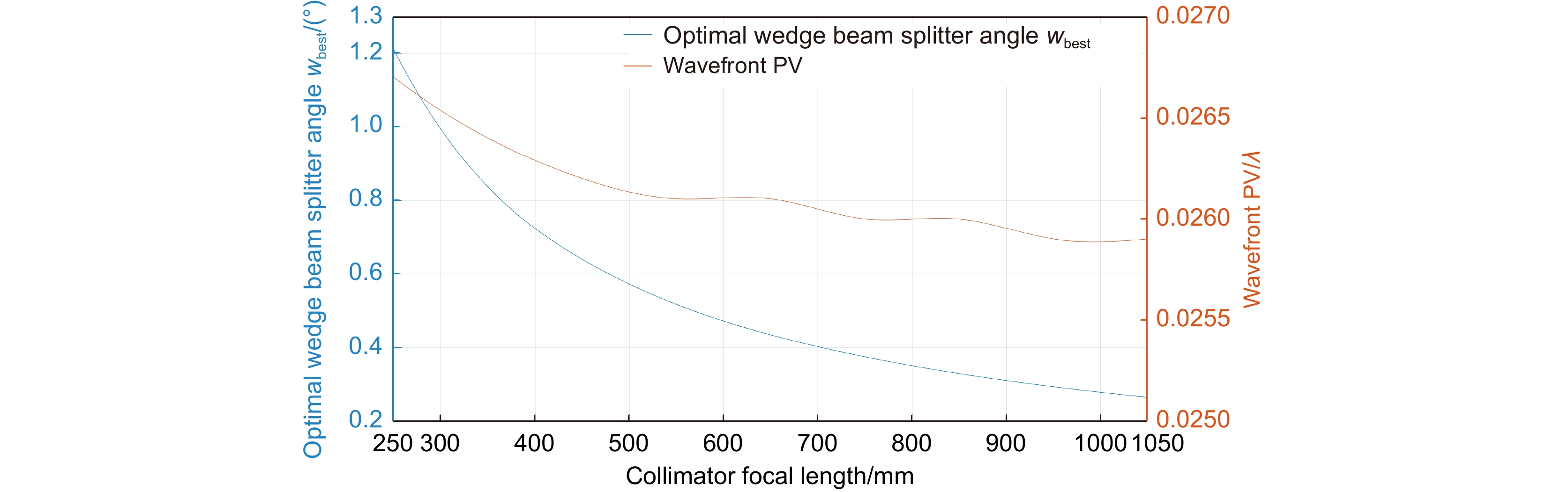
图 7 光楔最优楔角
${w_{{\rm{best}}}}$ 、光楔分光干涉系统波前PV与准直镜焦距关系曲线Figure 7. Relationship curve between the optimal wedge beam splitter angle
${w_{{\rm{best}}}}$ , wavefront PV of wedge beam splitter interference system and the focal length of the collimator
图 8 光楔分光中波红外Fizeau干涉仪照明光路
Figure 8. Illumination path of the wedge splitting medium wave infrared Fizeau interferometer
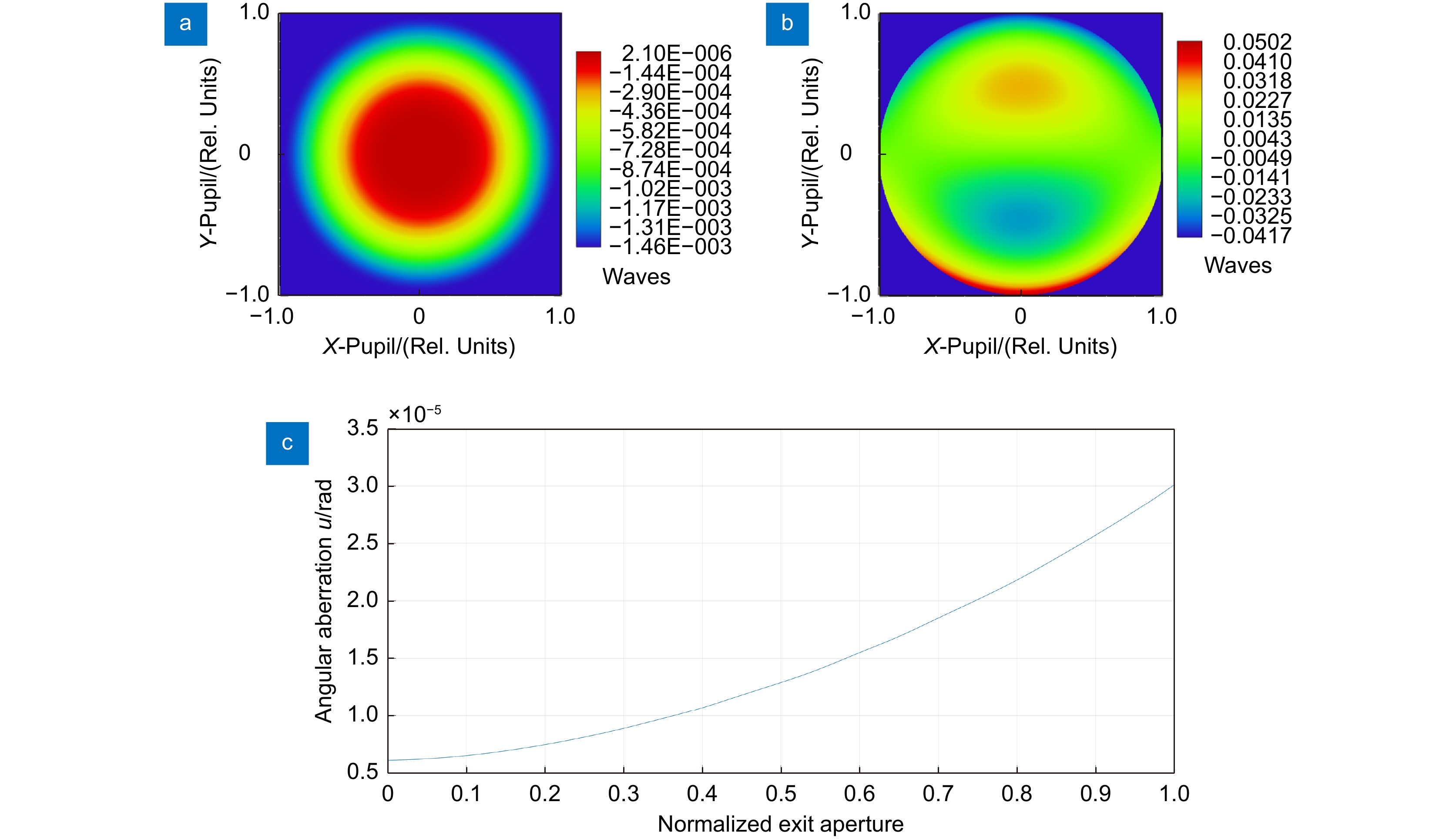
图 9 准直镜设计结果。(a) 准直镜0°视场准直波前PV;(b) 准直镜0.1°视场准直波前PV;(c) 准直镜归一化出射孔径角像差
Figure 9. Design results of the collimator. (a) PV of collimated wavefront for the collimator at 0° field of view; (b) PV of collimated wavefront for the collimator at 0.1° field of view; (c) Angular aberration of the normalized exit aperture for the collimator at 0° field of view
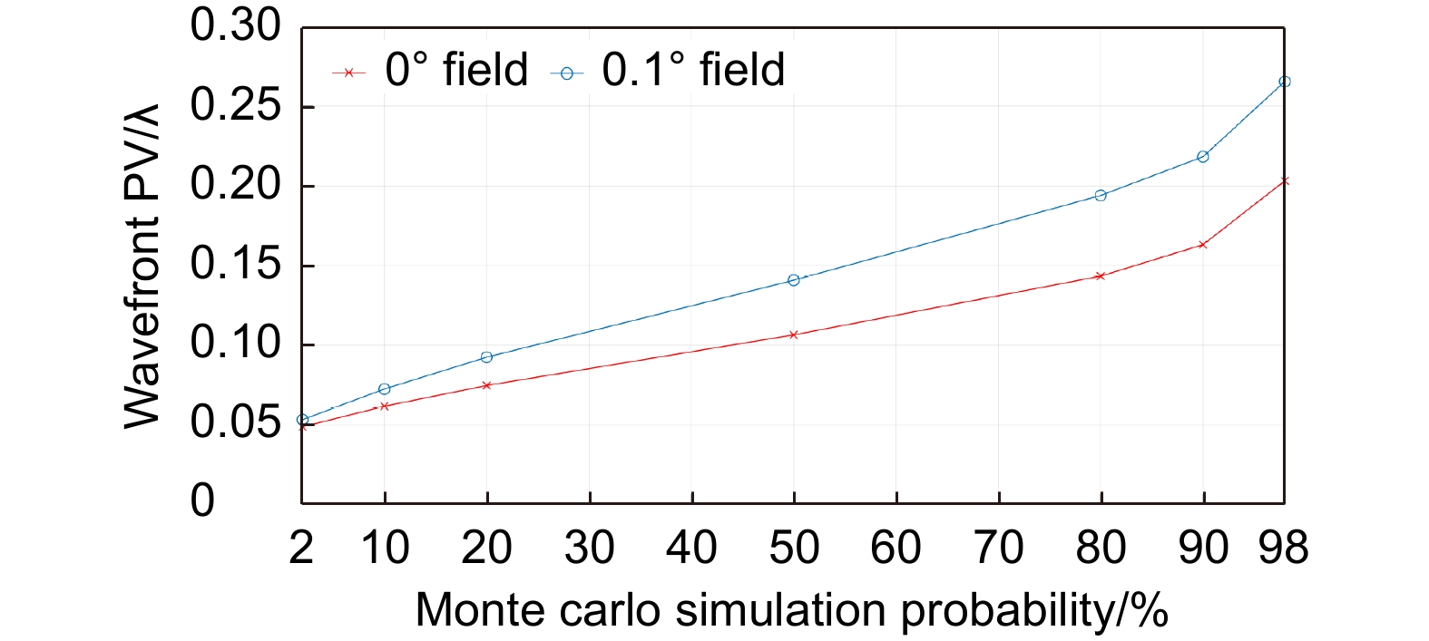
图 10 准直镜蒙特卡罗模拟公差分析
Figure 10. Monte carlo simulation tolerance analysis of the collimator
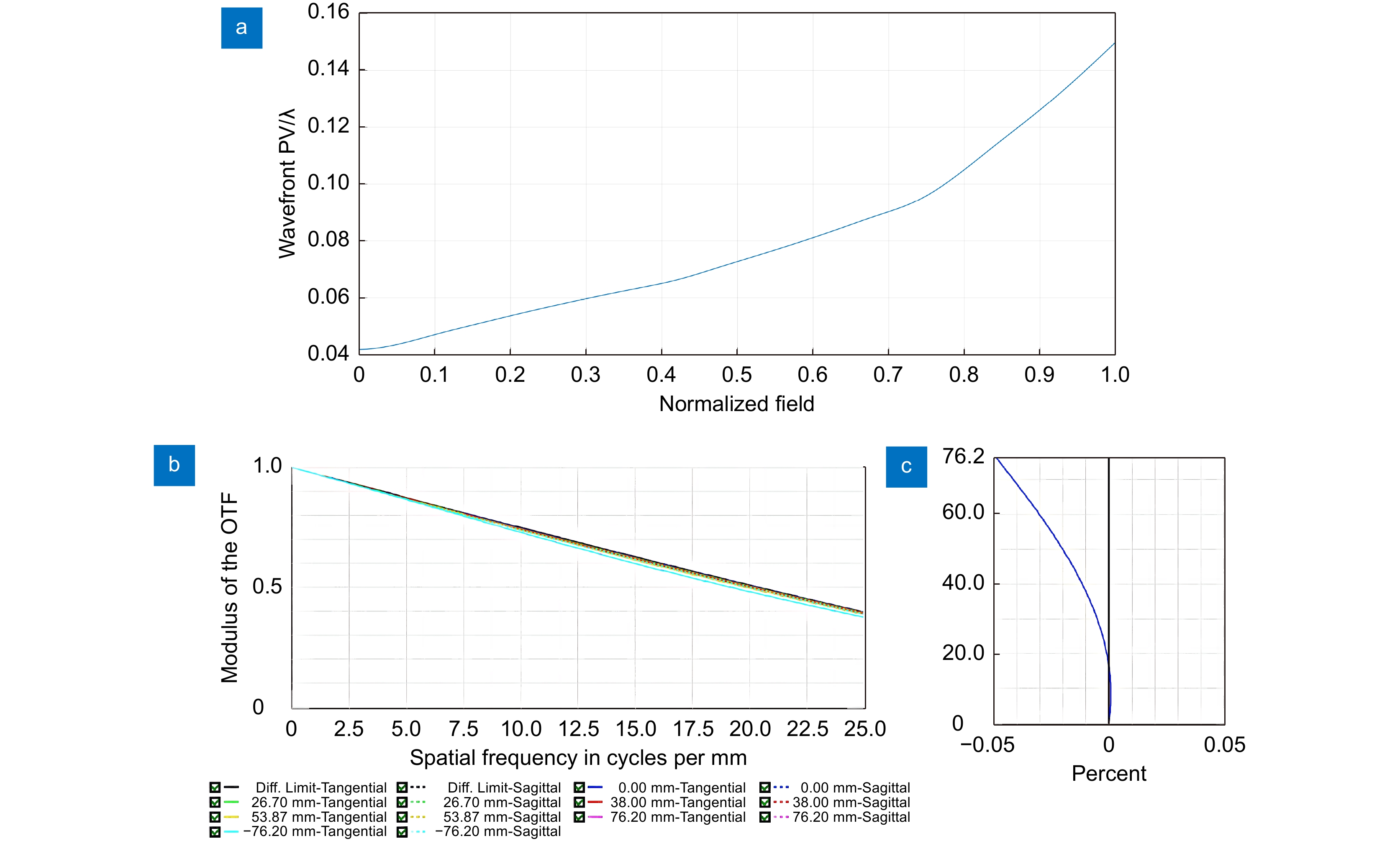
图 11 干涉仪成像光路像质评价。(a) 归一化视场成像波前PV;(b) MTF曲线;(c) 畸变曲线
Figure 11. Image quality evaluation of the interferometer imaging optical path. (a) Imaging wavefront PV of the normalized field; (b) MTF curve; (c) Distortion curve
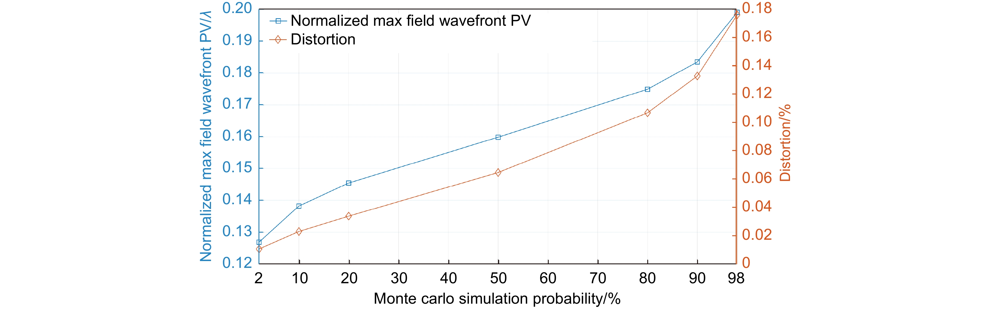
图 12 干涉仪成像光路蒙特卡罗模拟公差分析
Figure 12. Monte carlo simulation tolerance analysis of the interferometer imaging optical path
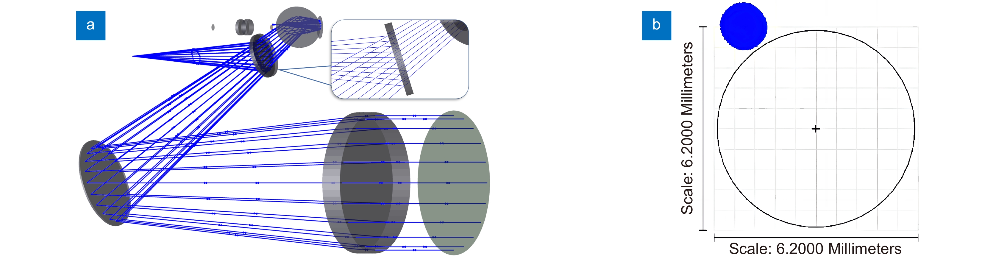
图 13 光楔元件杂散光分析示意图。(a) 光楔前后表面反射引入的杂散光示意图;(b) 孔径光阑面处光迹图
Figure 13. Stray light analysis diagram of the wedge beam splitter. (a) Schematic diagram of stray light introduced by reflection fromthe front and rear surfaces of the wedge beam splitter; (b) Light traces at the aperture diaphragm surface
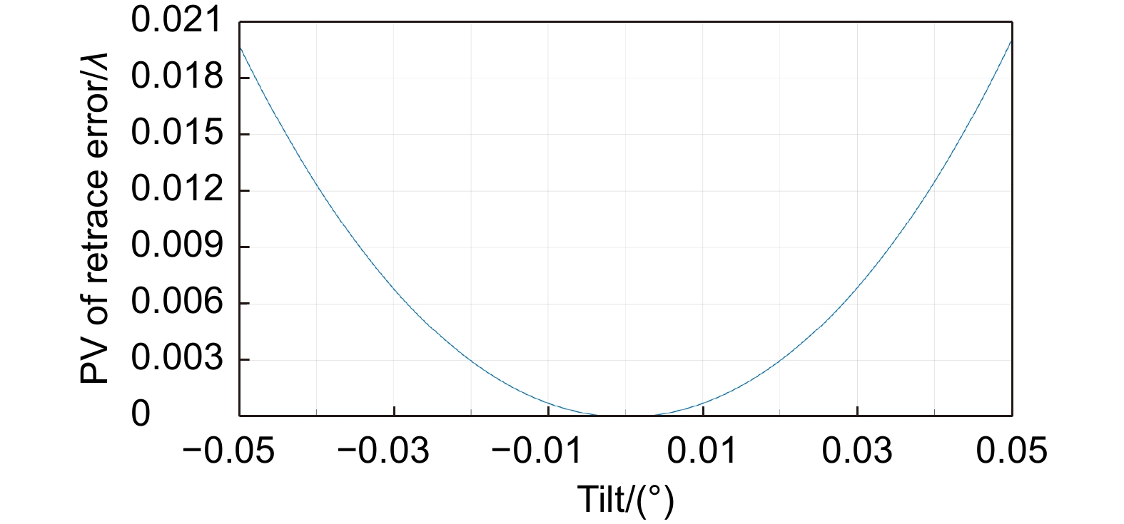
图 14 光楔分光中波红外Fizeau干涉仪回程误差
Figure 14. Retrace error of wedge splitting medium wave infrared Fizeau interferometer
表 1 在倾斜角T=20°时,平板型分束镜、光楔波前标准Zernike多项式系数
Table 1. Wavefront standard Zernike polynomial coefficients for the plate beam splitter and wedge beam splitter at a tilt angle of beam splitter T=20°
Plate beam splitter Wedge beam splitter Z5 0.0000 0.0000 Z6 0.0702 −0.0004 Z7 0.0117 0.0048 Z8 0.0000 0.0000 Z9 −0.0005 0.0009 Z10 0.0000 0.0000  下载: 导出CSV
表 2 准直镜、成像镜设计参数
Table 2. Collimator and imaging lens design parameters
Wavelength/μm F# Focal length/mm Collimator 3.39 5 762 Imaging lens 3.39 5.82 35
下载: 导出CSV
表 3 光楔分光中波红外Fizeau干涉仪光学系统镜头参数
Table 3. Lens data of the wedge splitting medium wave infrared Fizeau interferometer
Comment Surf. type Radius Thickness Material Semi-diameter Conic Tilt about X OBJ Standard Infinity Infinity - Infinity - - 1 Collimator Even asphere 1091.615 26.000 ZnSe 78.000 −1.862 - 2 Standard Infinity 580.000 - 78.000 - - 3 Wedge beam splitter Coordinate break - 0.000 - 0.000 - −17.500 4 Standard Infinity 5.000 CaF2 25.400 - - 5 Coordinate break - 0.000 - 0.000 - −0.200 6 Standard Infinity 0.000 - 25.400 - - 7 Coordinate break - 0.000 - 0.000 - 0.200 (P) 8 Coordinate break - 166.347 - 0.000 - 17.500(P) STO Standard Infinity 26.960 - 3.000 - - 10 Imaging lens Standard 37.274 6.000 ZnSe 9.000 - - 11 Standard 30.000 5.000 - 9.000 - - 12 Standard 164.984 5.000 ZnSe 9.000 - - 13 Standard −52.379 33.554 - 9.000 - - IMA Standard Infinity - - 3.503 - -
下载: 导出CSV
表 4 准直镜公差分配表
Table 4. Tolerance table for the collimator
Tolerance types Tolerance data Radius/% 0.1 Surface irregularity(RMS)/λ(λ=0.6328 μm) λ/40 Conic ±0.01 Thickness/mm ±0.05 Surface tilt/(°) ±0.05 Surface dec/mm ±0.05 Element tilt/(°) ±0.05 Element dec/mm ±0.05
下载: 导出CSV
-
[1] Lamare M. Interferometer for testing infrared materials and optical systems[J]. Proc SPIE, 1978, 136: 43−51. doi: 10.1117/12.956137
[2] 王之昊, 张文喜, 伍洲, 等. 激光测振仪中最小均方误差前向预测器的研究[J]. 光电工程, 2022, 49(5): 210391. doi: 10.12086/oee.2022.210391
Wang Z H, Zhang W X, Wu Z, et al. Research on the forward predictor of minimum mean square error in laser vibrometer[J]. Opto-Electron Eng, 2022, 49(5): 210391. doi: 10.12086/oee.2022.210391
[3] Malacara D. Optical Shop Testing[M]. 3rd ed. Hoboken: Wiley-Interscience, 2007: 17–19.
[4] Furuya A. Design of infrared interferometer[J]. Proc SPIE, 1990, 1320: 478−482. doi: 10.1117/12.22355
[5] 陈进榜, 陈磊, 王青, 等. 大孔径移相式CO2激光干涉仪[J]. 中国激光, 1998, 25(1): 31−36. doi: 10.3321/j.issn:0258-7025.1998.01.008
Chen J B, Chen L, Wang Q, et al. A large aperture phase-shifting CO2 laser interferometer[J]. Chin J Lasers, 1998, 25(1): 31−36. doi: 10.3321/j.issn:0258-7025.1998.01.008
[6] Wu Y Q, Zhang Y D, Wu F, et al. Far-infrared Fizeau interferometer for large aspheric mirror[J]. Proc SPIE, 2008, 7064: 70640S. doi: 10.1117/12.794415
[7] Yoder P, Vukobratovich D. Opto-Mechanical Systems Design[M]. 4th ed. Boca Raton: CRC Press, 2015: 131–132.
[8] 王生钊. 光学薄膜及其技术应用研究[M]. 北京: 中国水利水电出版社, 2020.
Wang S Z. Optical Thin Film and Its Technical Application Research[M]. Beijing: China Water Resources and Hydropower Press, 2020.
[9] 阙立志. 3~13μm宽带红外分束镜研究[J]. 红外技术, 2011, 33(12): 695−698. doi: 10.3969/j.issn.1001-8891.2011.12.004
Que L Z. Study of a 3 μm to 13 μm wideband infrared beamsplitter[J]. Infrared Technol, 2011, 33(12): 695−698. doi: 10.3969/j.issn.1001-8891.2011.12.004
[10] Polavarapu P L, Chen G C, Weibel S. Development, justification, and applications of a mid-infrared polarization-division interferometer[J]. Appl Spectrosc, 1994, 48(10): 1224−1235. doi: 10.1366/0003702944027381
[11] 朱波. 移相式斐索中波红外干涉仪关键技术及应用研究[D]. 南京: 南京理工大学, 2014.
Zhu B. Key technologies and applications of phase-shifted Fesol mid-wave infrared interferometer[D]. Nanjing: Nanjing University of Science and Technology, 2014.
[12] Selberg L A. Interferometer accuracy and precision[J]. Proc SPIE, 1991, 1400: 24−32. doi: 10.1117/12.26110
[13] 刘满林, 杨旺, 许伟才. 干涉仪成像畸变引起测量误差的校正方法[J]. 光学 精密工程, 2011, 19(10): 2349−2354. doi: 10.3788/OPE.20111910.2349
Liu M L, Yang W, Xu W C. Calibration of measuring error caused by interferometric imaging distortion[J]. Opt Precis Eng, 2011, 19(10): 2349−2354. doi: 10.3788/OPE.20111910.2349
[14] 李景镇. 光学手册[M]. 西安: 陕西科学技术出版社, 1986: 865–867.
Li J Z. Optical Manual[M]. Xi’an: Shaanxi Science and Technology Press, 1986: 865–867.
[15] 李金鹏, 王鑫蕊, 杨永兴, 等. 一种用于可见-红外光同步成像系统的楔板型分束镜: CN213182178U[P]. 2021-05-11.
Li J P, Wang X R, Yang Y X, et al. A wedge plate type beam splitter for visible-infrared simultaneous imaging system: CN213182178U[P]. 2021-05-11.
[16] Howard J W. Formulas for the coma and astigmatism of wedge prisms used in converging light[J]. Appl Opt, 1985, 24(23): 4265−4268. doi: 10.1364/AO.24.004265
[17] 蔡志华. 基于单光楔补偿拼接检测大口径凸非球面反射镜技术的研究[D]. 长春: 中国科学院大学(中国科学院长春光学精密机械与物理研究所), 2021. https://doi.org/10.27522/d.cnki.gkcgs.2021.000075.
Cai Z H. Research on the technology of testing large convex aspherical mirror by single wedge compensation stitching method[D]. Changchun: Changchun Institute of Optics, Fine Mechanics and Physics, Chinese Academy of Sciences, 2021. https://doi.org/10.27522/d.cnki.gkcgs.2021.000075.
-


 点击扫一扫
点击扫一扫
图(15)
表(4)
计量
- 文章访问数: 6862
- PDF下载数: 1091
- 施引文献: 0


