-
摘要
偏光全息拥有记录振幅、相位和偏振信息的能力,在数据存储、偏振光成像等领域具有重要的应用前景。除此之外,它也具备光场调控方面的能力,可以调控具有螺旋相位分布和空间偏振分布等特殊光场,这类特殊光场在光通信、粒子操纵及光子纠缠等领域有广泛的应用前景,目前也有很多研究聚焦于如何生成这类光束。本文介绍了利用偏光全息制备矢量光束、标量涡旋光束和矢量涡旋光束的最新研究进展。基于偏光全息进行光场调控的方法,具有制备过程操作简单、光学系统体积小、制作成本低的优势,为特殊光场制造提供新的思路。
Abstract
Polarization holography has important application prospects in the field of data storage and polarized light imaging due to its ability to record amplitude, phase and polarization information. In addition, it also has the ability to regulate light fields, which can regulate special light fields with helical phase distribution and spatial polarization distribution. Such special light fields have broad application prospects in the fields of optical communication, particle manipulation, photon entanglement, etc. There is also a lot of research focused on how to generate such beams. The latest research progress in preparing vector beams, scalar vortex beams, and vector vortex beams by using polarization holography is introduced in this paper. The light field regulation method based on polarization holography has the advantages of a simple fabrication process, the small size of the optical system and low production cost, which provides a new idea for the manufacture of special light fields.
-
Key words:
- polarization holography /
- light field regulation /
- vector vortex /
- vector light field /
- optical vortex
-
Overview
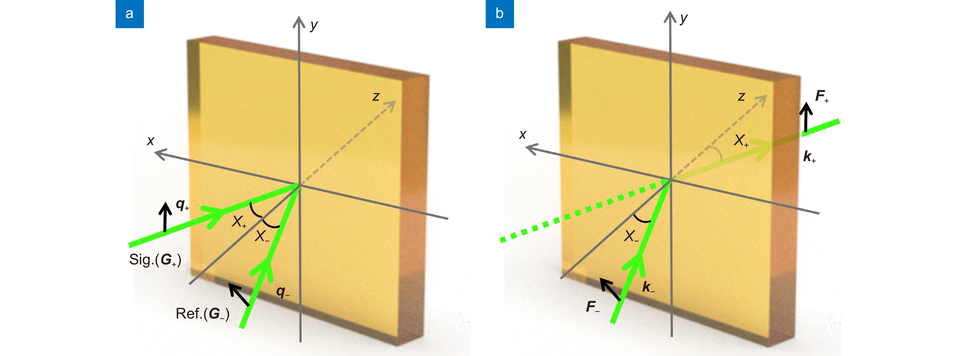
Overview: Polarization holography has important application prospects in the field of data storage and polarized light imaging due to its ability to record amplitude, phase, and polarization information. In addition, it also has the ability to regulate light fields, which can regulate special light fields with helical phase distribution and spatial polarization distribution. Such special light fields have broad application prospects in the fields of optical communication, particle manipulation, photon entanglement, etc. There is also a lot of researches focused on how to generate such beams, such as helical phase plates, mode conversion, spatial light modulators, etc. However, the traditional method requires the construction of a relatively large optical system, which limits its application in fields such as integrated optics. The introduction of the beam preparation method of polarization holography can reduce the volume of the optical system to a certain extent. At the same time, the use of polarization-sensitive materials with the ability to record multi-dimensional information greatly reduces the cost on the one hand. On the other hand, it is easy to operate during the preparation process, which is expected to be an ideal material for beam preparation to some extent. Based on the introduction of the principle of faithful reconstruction of any polarization state by polarization holography, this paper reviews the research progress of generating vector beams, scalar vortex beams, and vector vortex beams based on polarization holography in the past two years. Faithful reconstruction for any polarization state refers to under the incident into the polarization-sensitive material at 90 degrees interference angle between the signal and reference waves, the recording and reading waves are p-polarized and the reconstruction wave can be reconstructed correctly. Phenanthrenequinone-doped polymethyl methacrylate photopolymer (PQ/PMMA) is used as a recording material in the experiment. First, the single control ability of polarization holography in polarization and phase is demonstrated respectively, and then the ability of polarization holography to control both polarization and phase at the same time is further introduced. Based on the characteristics of polarization holography, the signal optical path is regulated, and the vector beam, scalar vortex beam, and vector vortex beam are generated by setting the initial azimuth angle of the rotating components and adjusting their relative rotational angular velocity under dynamic exposure. In the fabrication process, the desired beam can be generated by simply controlling the parameters of some devices. Finally, the ability and prospect of generating special light fields based on polarization holography are briefly summarized and discussed.
-

-
图 2 实验中的偏振敏感聚合物材料[65]。(a) 立方材料和(b)曝光前的分子分布模型;E,光场的电矢量;(c) 曝光后的分子分布模型
Figure 2. Polarization-sensitive polymer material in our experiment[65]. (a) Cubic material and (b) the molecular distribution model before exposure; E, electric vector of the light field; (c) Molecular distribution model after exposure. Figure adapted with permission from ref. [65] © Optica Publishing Group
图 4 偏振阶数p=1和初始方位角θ0=15◦的矢量光束的强度和偏振分布[65]。(a), (f) 分别模拟和实验强度分布;(b)~(e) 模拟中P=15°、45°、75°和105°处偏振片后的强度分布;(g)~(j) 对应的实验结果
Figure 4. Intensity and polarization distributions of the vector beam with a polarization order of p=1 and an original azimuthal θ0=15°[65]. (a), (f) Simulation and experimental intensity distributions, respectively; (b)~(e) Intensity distributions after the polarizer at P = 15°, 45°, 75°, and 105° in simulation; (g)~(j) Corresponding experimental results. Figure reprinted with permission from ref. [65] © Optica Publishing Group
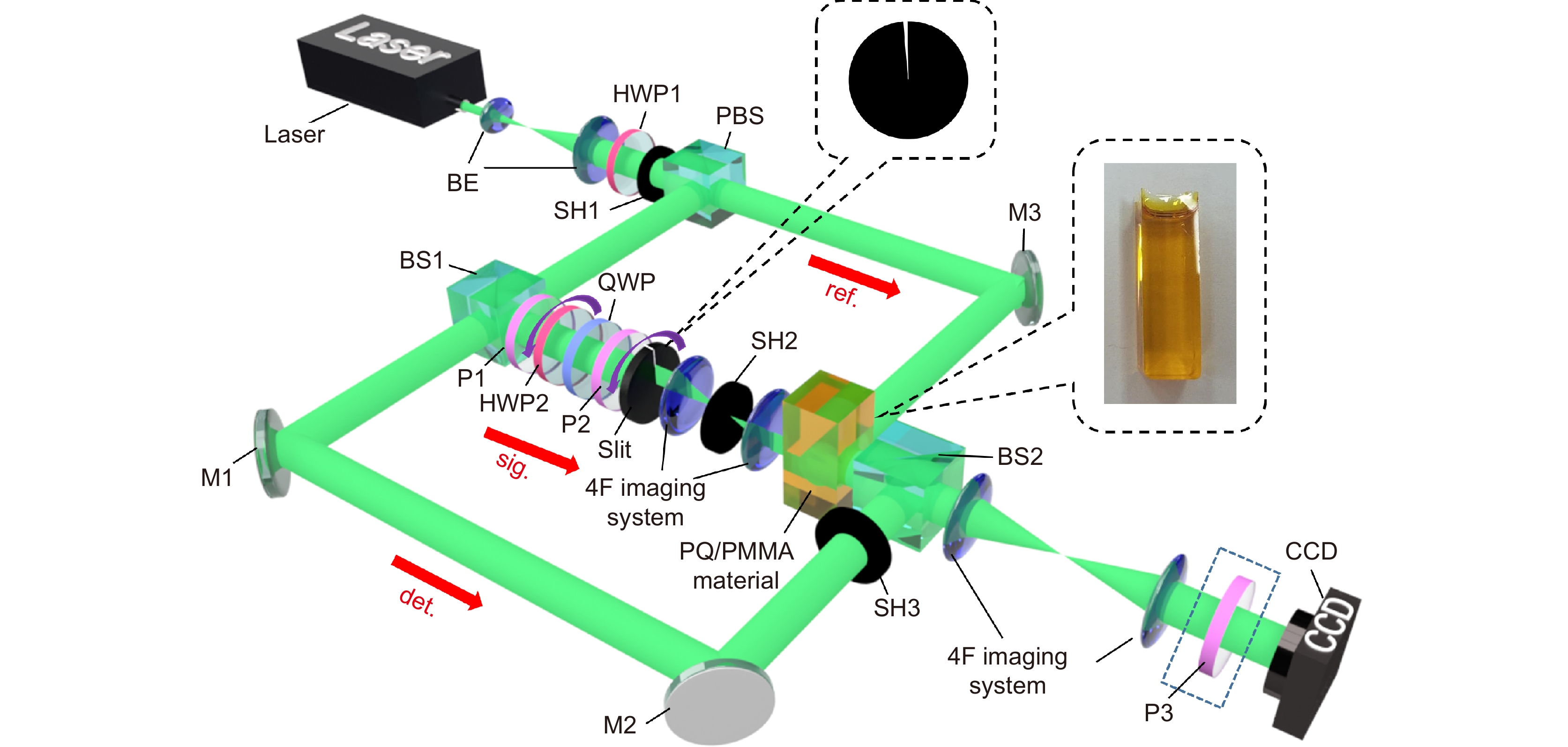
图 5 产生涡旋光束的实验装置[60]。其中:PBS代表偏振分束器,BE是扩束器,HWP是半波片,QWP 是四分之一波片,P是偏振片,SH是快门,BS是分束器,4F imaging system是一个线性光学成像系统, M是反射镜。材料为立方型偏振敏感聚合物材料(PQ/PMMA)。sig.表示信号光路,ref.表示记录和读取光路,det.表示检测光路
Figure 5. Experimental setup for generating vortex beam[60]. Where PBS represents polarization beam splitter, BE is beam expander, HWP is half wave plate, QWP is quarter wave plate, P is polarizer, SH is shutter, BS is beam splitter, the 4F imaging system is a linear optical information processing system and M is mirror. The material is cubic-shaped polarization-sensitive polymer material (PQ/ PMMA). Figure reprinted with permission from ref. [60] © Optica Publishing Group
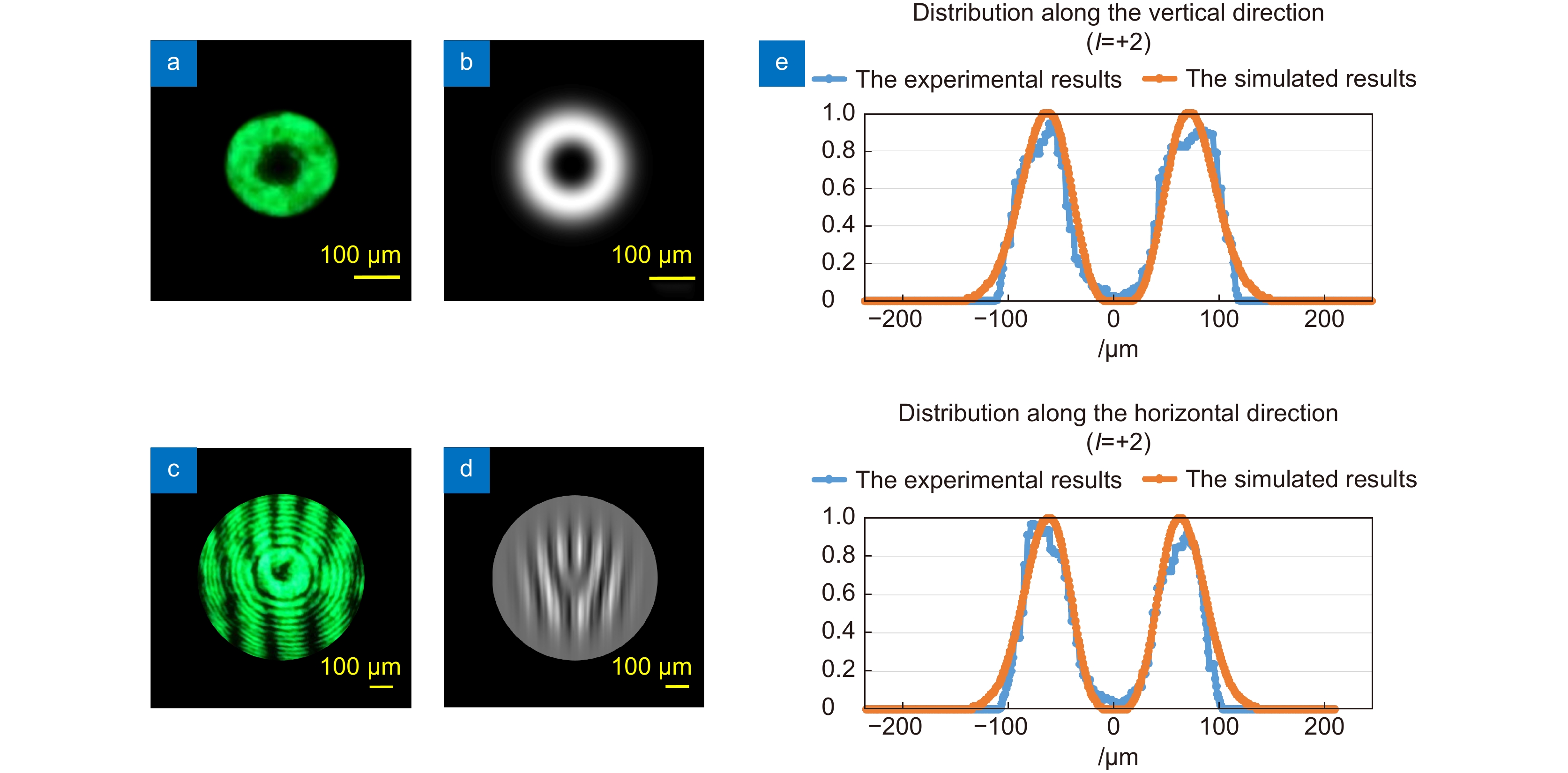
图 6 l=+2的标量涡旋光束的强度分布图[60]。(a) 实验结果;(b) 模拟结果;平面波与标量涡旋光束的干涉图,(c) 实验结果;(d) 模拟结果;(e) 沿垂直方向(上)和水平方向(下)的强度分布
Figure 6. Intensity pattern about l=+2 scalar vortex beam[60]. (a) Experimental result; (b) Simulated result; the interference pattern between plane wave and scalar vortex beam; (c) Experimental result; (d) Simulated result; (e) Intensity distribution along the vertical direction (upper) and the horizontal direction (lower). Figure reprinted with permission from ref. [60] © Optica Publishing Group
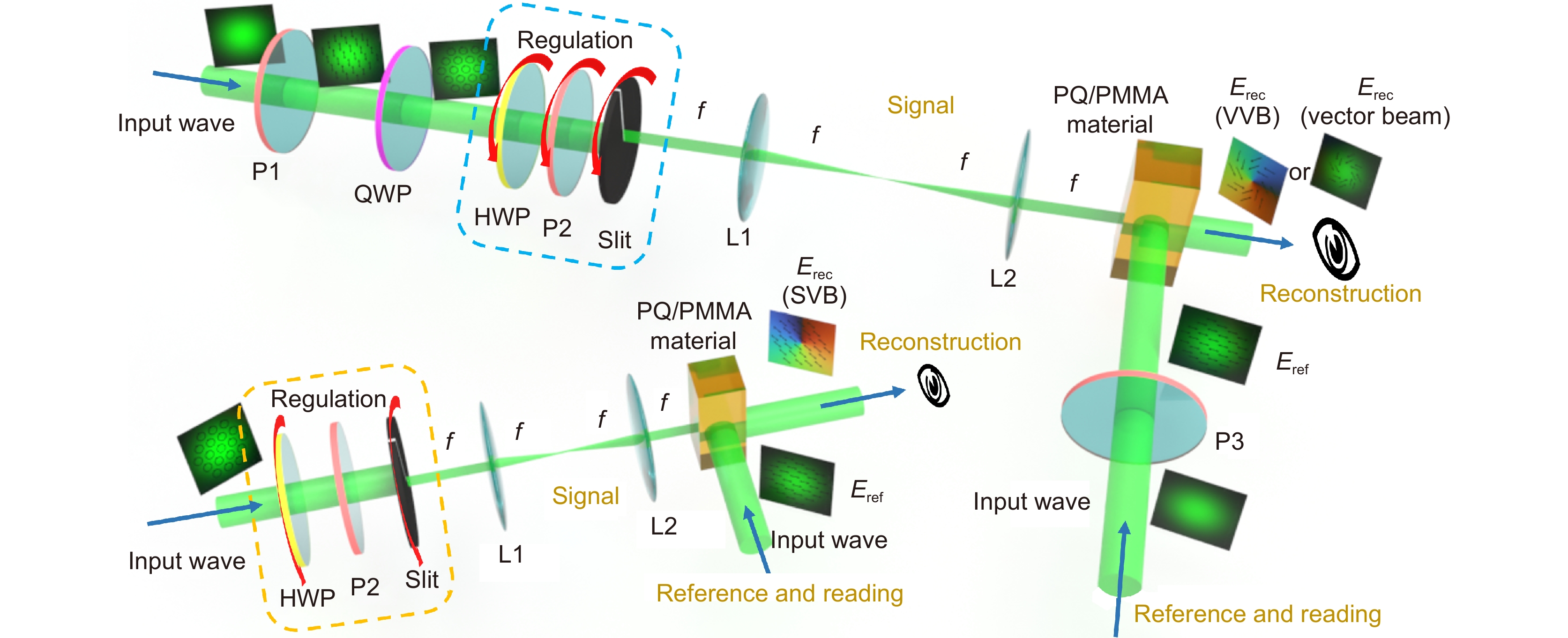
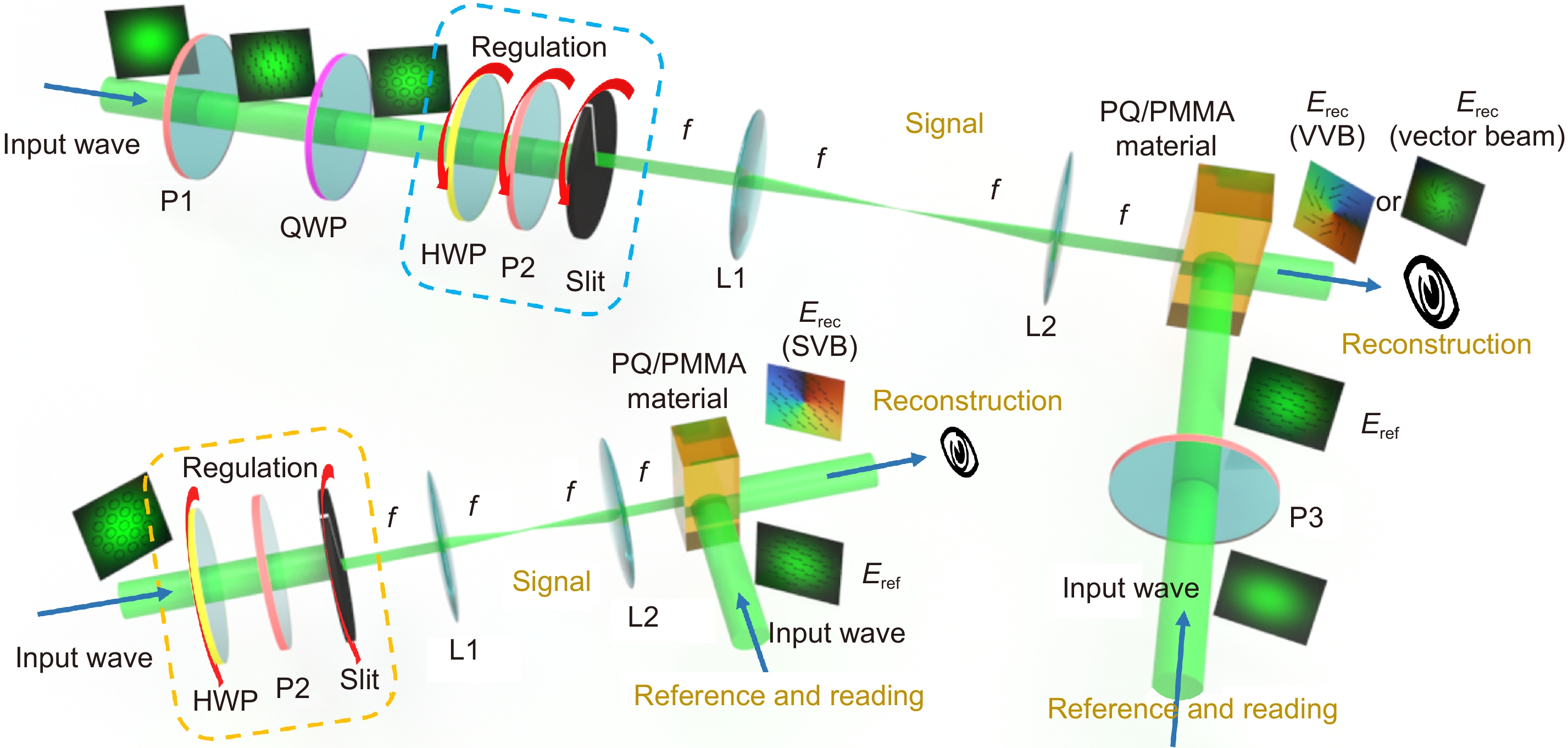
图 7 产生特殊光束的实验装置[67]。其中:HWP是半波片,QWP是四分之一波片,P是偏振片,L是透镜。材料为立方型偏振敏感聚合物材料(PQ/PMMA)。上面的装置用于制备矢量涡旋光束和矢量光束,左下角的装置用于制备标量涡旋光束。它们之间的主要区别在于P2是否旋转
Figure 7. Experimental setup for generating special beams[67]. Where HWP is half wave plate, QWP is quarter wave plate, P is polarizer, L is lens. The material is cubic-shaped polarization-sensitive polymer material (PQ/PMMA). The setup for the upper point is used to prepare vector vortex beams and vector beams, and the setup in the lower-left corner is used to prepare scalar vortex beams. The main difference between them is whether P2 is rotated. Figure reprinted with permission from ref. [67] © Optica Publishing Group
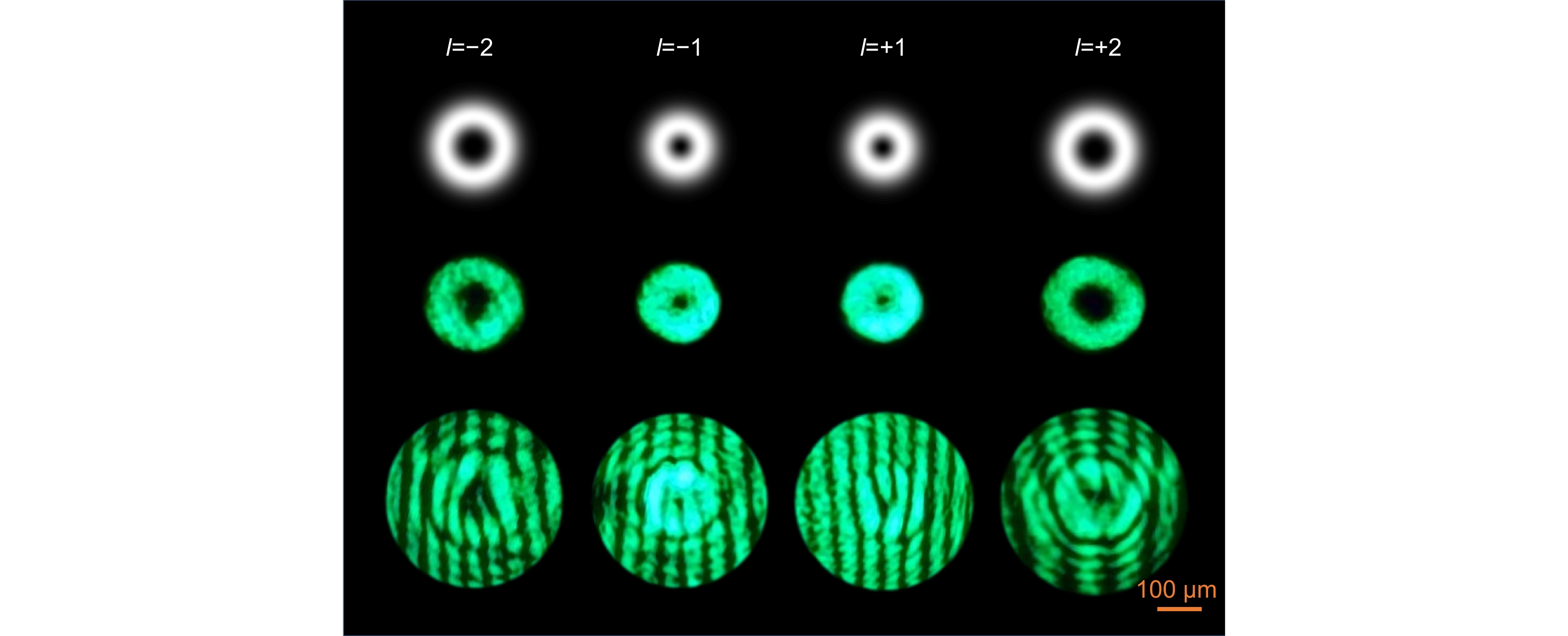
图 8 位于基本庞加莱球的(π/2, 0)处l=−2、−1、+1和+2的标量涡旋光束的模拟结果、实验结果和实验干涉图案[67]
Figure 8. Simulation results, experimental results, and experimental interference patterns of l=−2, −1, +1, and +2 of scalar vortex beams at (π/2, 0) of the basic Poincaré Sphere[67]. Figure reprinted with permission from ref. [67] © Optica Publishing Group
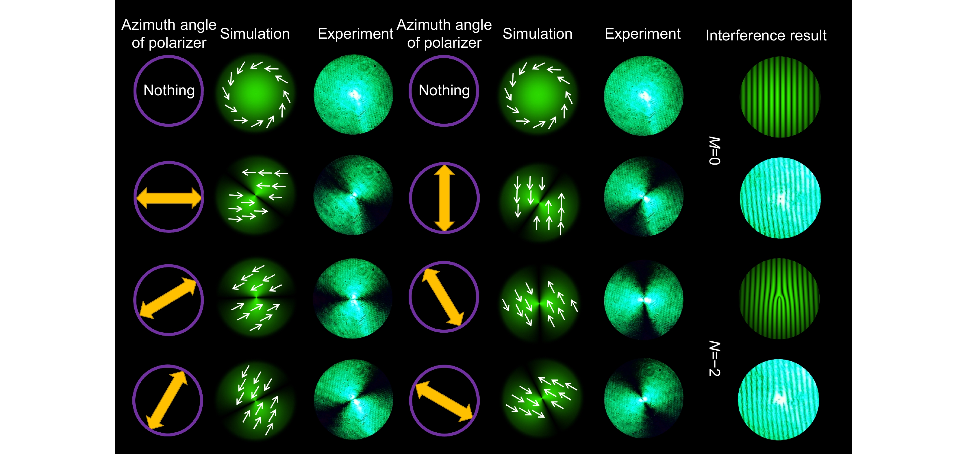
图 9 杂化庞加莱球(l=−1和p=+1)球面上(2π/3, 0)处的矢量涡旋光束结果。通过不同方向的P的实验和模拟结果右侧的结果是实验得到的矢量涡旋光束分别与右旋和左旋圆偏振平面波干涉图案[67]
Figure 9. Results of the vector vortex beam at (2π/3, 0) on the sphere of a hybrid-order Poincaré Sphere (l=−1 and p=+1). Experimental and simulated results for a different orientational P. Results on the right are forked gratings of the experimental vector vortex beam interfered with the right- and left-handed circularly-polarized plane waves, respectively[67]. Figure adapted with permission from ref. [67] © Optica Publishing Group
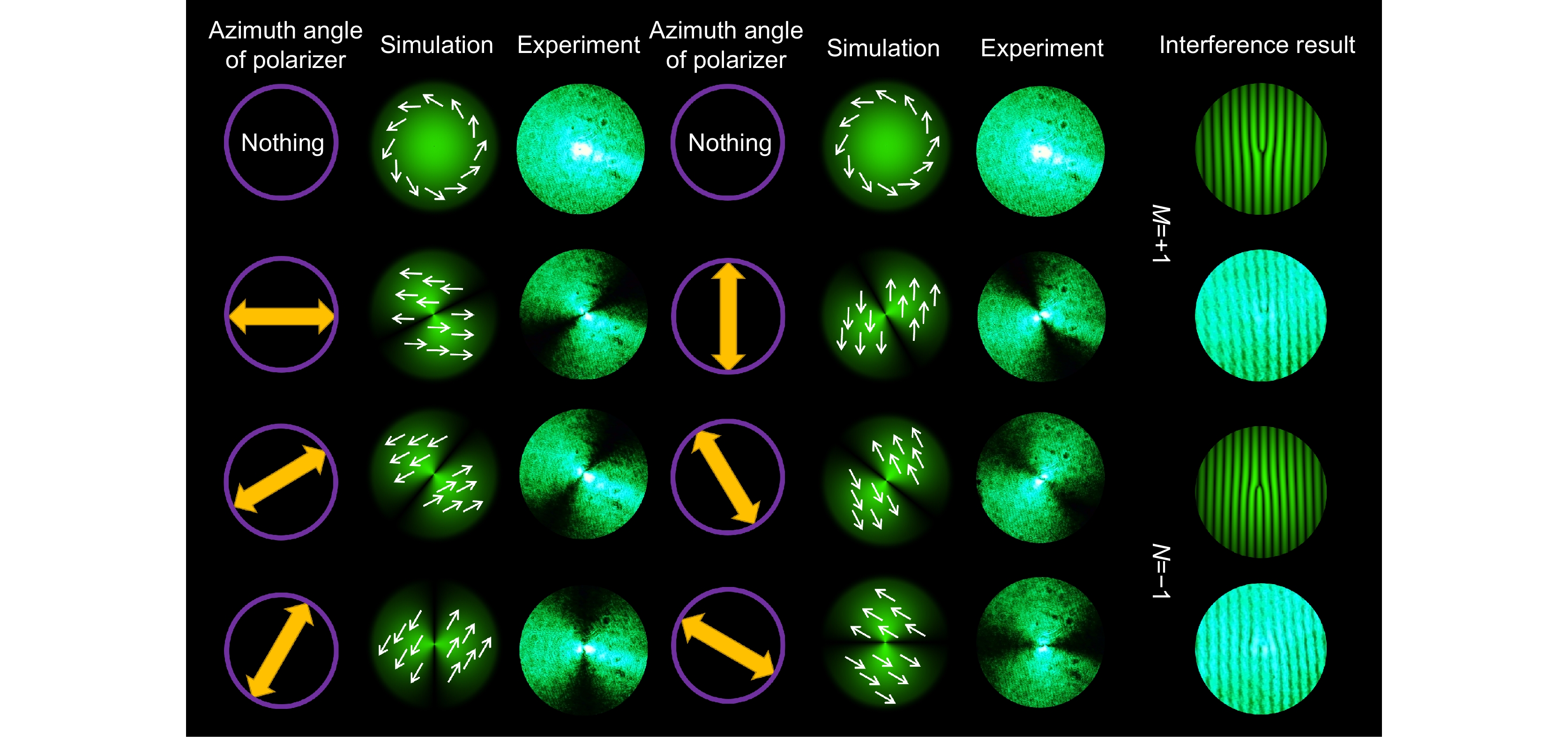
图 10 高阶庞加莱球(p=+1)球面上(4π/3, 0)处矢量光束的结果。通过不同方向的P的实验和模拟结果,右侧的结果是实验得到的矢量光束分别与右旋和左旋圆偏振平面波干涉图案[67]
Figure 10. Results of the vector beam at (4π/3, 0) on the sphere of a higher-order Poincaré Sphere (p=+1). Experimental and simulated results for a different orientational P. Results on the right are forked gratings of the experimental vector beam interfered with the right- and left-handed circularly-polarized plane waves, respectively[67]. Figure adapted with permission from ref. [67] © Optica Publishing Group
表 1 实现任意偏振态忠实再现的条件
Table 1. Condition about faithful reconstruction of realizing any polarization state
记录 G+∝αeiδs+βp+ G−∝p− 读取 F−∝p− 再现 F+∝B(αeiδs+βp+)+(A+B)βcos$\chi $p+ F+ ($\chi $=90°)∝B(αeiδs+βp+) 表 2 实验中产生的不同标量涡旋光束对应的实验参数和光功率[67]
Table 2. Experimental parameters and power corresponding to different scalar vortex beams generated in the experiment[67]. Table reprinted with permission from ref. [67] © Optica Publishing Group
l阶的标量涡旋光束 (ωH: ωs=l/2: 1) HWP2 ωH(°/s) /旋转方向 Slit ωs(°/s) /旋转方向 光功率/nW l = −2 (−1∶1) 1.5 /顺时针 1.5 /逆时针 ~290 l = −1 (−1∶2) 1.5 /顺时针 3 /逆时针 ~240 l = +1 (1: 2) 1.5 /逆时针 3 /逆时针 ~240 l = +2 (1: 1) 1.5 /逆时针 1.5 /逆时针 ~280 表 3 实验中产生的不同光束对应的实验参数和光功率[67]
Table 3. Experimental parameters and power corresponding to different beams generated in the experiment[67]. Table adapted with permission from ref. [67] © Optica Publishing Group
不同l和p的矢量涡旋光束
(ωP: ωH: ωs=p: (l−p)/2: 1)P2
ωP(°/s) /旋转方向HWP2
ωH(°/s) /旋转方向Slit
ωs(°/s) /旋转方向P2
θ0/rad光功率 l = −1, p = +1 (1: −1: 1) 2 /逆时针 2 /顺时针 2 /逆时针 π/3 ~1.3 μW l = 0, p = +1 (2: −1: 2) 4 /逆时针 2 /顺时针 4 /逆时针 2π/3 ~570 nW -
参考文献
[1] Zhan Q W. Cylindrical vector beams: from mathematical concepts to applications[J]. Adv Opt Photonics, 2009, 1(1): 1−57. doi: 10.1364/AOP.1.000001
[2] Meier M, Romano V, Feurer T. Material processing with pulsed radially and azimuthally polarized laser radiation[J]. Appl Phys A, 2007, 86(3): 329−334. doi: 10.1007/s00339-006-3784-9
[3] Lou K, Qian S X, Wang X L, et al. Two-dimensional microstructures induced by femtosecond vector light fields on silicon[J]. Opt Express, 2012, 20(1): 120−127. doi: 10.1364/OE.20.000120
[4] Varin C, Piché M. Acceleration of ultra-relativistic electrons using high-intensity TM01 laser beams[J]. Appl Phys B, 2002, 74(S1): s83−s88. doi: 10.1007/s00340-002-0906-8
[5] Novotny L, Beversluis M R, Youngworth K S, et al. Longitudinal field modes probed by single molecules[J]. Phys Rev Lett, 2001, 86(23): 5251−5254. doi: 10.1103/PhysRevLett.86.5251
[6] Ciattoni A, Crosignani B, Di Porto P, et al. Azimuthally polarized spatial dark solitons: exact solutions of Maxwell's equations in a Kerr medium[J]. Phys Rev Lett, 2005, 94(7): 073902. doi: 10.1103/PhysRevLett.94.073902
[7] Kawauchi H, Yonezawa K, Kozawa Y, et al. Calculation of optical trapping forces on a dielectric sphere in the ray optics regime produced by a radially polarized laser beam[J]. Opt Lett, 2007, 32(13): 1839−1841. doi: 10.1364/OL.32.001839
[8] Zhan Q W. Trapping metallic Rayleigh particles with radial polarization[J]. Opt Express, 2004, 12(15): 3377−3382. doi: 10.1364/OPEX.12.003377
[9] Gabriel C, Aiello A, Zhong W, et al. Entangling different degrees of freedom by quadrature squeezing cylindrically polarized modes[J]. Phys Rev Lett, 2011, 106(6): 060502. doi: 10.1103/PhysRevLett.106.060502
[10] Cardano F, Karimi E, Slussarenko S, et al. Polarization pattern of vector vortex beams generated by q-plates with different topological charges[J]. Appl Opt, 2012, 51(10): C1−C6. doi: 10.1364/AO.51.0000C1
[11] Rumala Y S, Milione G, Nguyen T A, et al. Tunable supercontinuum light vector vortex beam generator using a q-plate[J]. Opt Lett, 2013, 38(23): 5083−5086. doi: 10.1364/OL.38.005083
[12] Wang X L, Ding J P, Ni W J, et al. Generation of arbitrary vector beams with a spatial light modulator and a common path interferometric arrangement[J]. Opt Lett, 2007, 32(24): 3549−3551. doi: 10.1364/OL.32.003549
[13] Machavariani G, Lumer Y, Moshe I, et al. Spatially-variable retardation plate for efficient generation of radially- and azimuthally-polarized beams[J]. Opt Commun, 2008, 281(4): 732−738. doi: 10.1016/j.optcom.2007.10.088
[14] 谭巧, 徐启峰, 谢楠. 亚波长径向偏振光栅的设计[J]. 光电工程, 2017, 44(3): 345−350. doi: 10.3969/j.issn.1003-501X.2017.03.010
Tan Q, Xu Q F, Xie N. Design of sub-wavelength radially polarized grating[J]. Opto-Electron Eng, 2017, 44(3): 345−350. doi: 10.3969/j.issn.1003-501X.2017.03.010
[15] Phua P B, Lai W J. Simple coherent polarization manipulation scheme for generating high power radially polarized beam[J]. Opt Express, 2007, 15(21): 14251−14256. doi: 10.1364/OE.15.014251
[16] Allen L, Beijersbergen M W, Spreeuw R J C, et al. Orbital angular momentum of light and the transformation of Laguerre-Gaussian laser modes[J]. Phys Rev A, 1992, 45(11): 8185−8189. doi: 10.1103/physreva.45.8185
[17] Nye J F, Berry M V. Dislocations in wave trains[J]. Proc Roy Soc A Math Phys Eng Sci, 1974, 336(1605): 165−190. doi: 10.1098/rspa.1974.0012
[18] Coullet P, Gil L, Rocca F, et al. Optical vortices[J]. Opt Commun, 1989, 73(5): 403−408. doi: 10.1016/0030-4018(89)90180-6
[19] Zhao Y F, Wang J. High-base vector beam encoding/decoding for visible-light communications[J]. Opt Lett, 2015, 40(21): 4843−4846. doi: 10.1364/OL.40.004843
[20] Milione G, Nguyen T A, Leach J, et al. Using the nonseparability of vector beams to encode information for optical communication[J]. Opt Lett, 2015, 40(21): 4887−4890. doi: 10.1364/OL.40.004887
[21] 郭忠义, 龚超凡, 刘洪郡, 等. OAM光通信技术研究进展[J]. 光电工程, 2020, 47(3): 190593. doi: 10.12086/oee.2020.190593
Guo Z Y, Gong C F, Liu H J, et al. Research advances of orbital angular momentum based optical communication technology[J]. Opto-Electron Eng, 2020, 47(3): 190593. doi: 10.12086/oee.2020.190593
[22] Beijersbergen M W, Allen L, van der Veen H E L O, et al. Astigmatic laser mode converters and transfer of orbital angular momentum[J]. Opt Commun, 1993, 96(1–3): 123−132. doi: 10.1016/0030-4018(93)90535-D
[23] Guo Z Y, Qu S L, Liu S T. Generating optical vortex with computer-generated hologram fabricated inside glass by femtosecond laser pulses[J]. Opt Commun, 2007, 273(1): 286−289. doi: 10.1016/j.optcom.2006.12.023
[24] Heckenberg N R, McDuff R, Smith C P, et al. Generation of optical phase singularities by computer-generated holograms[J]. Opt Lett, 1992, 17(3): 221−223. doi: 10.1364/OL.17.000221
[25] Carpentier A V, Michinel H, Salgueiro J R, et al. Making optical vortices with computer-generated holograms[J]. Am J Phys, 2008, 76(10): 916−921. doi: 10.1119/1.2955792
[26] Beijersbergen M W, Coerwinkel R P C, Kristensen M, et al. Helical-wavefront laser beams produced with a spiral phaseplate[J]. Opt Commun, 1994, 112(5–6): 321−327. doi: 10.1016/0030-4018(94)90638-6
[27] Hao X, Kuang C F, Wang T T, et al. Phase encoding for sharper focus of the azimuthally polarized beam[J]. Opt Lett, 2010, 35(23): 3928−3930. doi: 10.1364/OL.35.003928
[28] Zhao Z, Wang J, Li S H, et al. Metamaterials-based broadband generation of orbital angular momentum carrying vector beams[J]. Opt Lett, 2013, 38(6): 932−934. doi: 10.1364/OL.38.000932
[29] Qiu C W, Palima D, Novitsky A, et al. Engineering light-matter interaction for emerging optical manipulation applications[J]. Nanophotonics, 2014, 3(3): 181−201. doi: 10.1515/nanoph-2013-0055
[30] Zhang B X, Chen Z Z, Sun H, et al. Vectorial optical vortex filtering for edge enhancement[J]. J Opt, 2016, 18(3): 035703. doi: 10.1088/2040-8978/18/3/035703
[31] Liu Y, Cline D, He P. Vacuum laser acceleration using a radially polarized CO2 laser beam[J]. Nucl Instrum Methods Phys Res, 1999, 424(2–3): 296−303. doi: 10.1016/S0168-9002(98)01433-8
[32] Tang J, Ming Y, Chen Z X, et al. Entanglement of photons with complex spatial structure in Hermite-Laguerre-Gaussian modes[J]. Phys Rev A, 2016, 94(1): 012313. doi: 10.1103/PhysRevA.94.012313
[33] Zhang Y, Li P, Liu S, et al. Unveiling the photonic spin Hall effect of freely propagating fan-shaped cylindrical vector vortex beams[J]. Opt Lett, 2015, 40(19): 4444−4447. doi: 10.1364/OL.40.004444
[34] Liu Y C, Ke Y G, Luo H L, et al. Photonic spin Hall effect in metasurfaces: a brief review[J]. Nanophotonics, 2016, 6(1): 51−70. doi: 10.1515/nanoph-2015-0155
[35] Kim D, Choi H, Brendel T, et al. Advances in optical engineering for future telescopes[J]. Opto-Electron Adv, 2021, 4(6): 210040. doi: 10.29026/oea.2021.210040
[36] Chen H, Hao J J, Zhang B F, et al. Generation of vector beam with space-variant distribution of both polarization and phase[J]. Opt Lett, 2011, 36(16): 3179−3181. doi: 10.1364/OL.36.003179
[37] Oron R, Blit S, Davidson N, et al. The formation of laser beams with pure azimuthal or radial polarization[J]. Appl Phys Lett, 2000, 77(21): 3322−3324. doi: 10.1063/1.1327271
[38] Lin X J, Feng Q C, Zhu Y, et al. Diode-pumped wavelength-switchable visible Pr3+: YLF laser and vortex laser around 670 nm[J]. Opto-Electron Adv, 2021, 4(4): 210006. doi: 10.29026/oea.2021.210006
[39] Lin X, Liu J P, Hao J Y, et al. Collinear holographic data storage technologies[J]. Opto-Electron Adv, 2020, 3(3): 190004. doi: 10.29026/oea.2020.190004
[40] Horimai H, Tan X D, Li J. Collinear holography[J]. Appl Opt, 2005, 44(13): 2575−2579. doi: 10.1364/AO.44.002575
[41] 魏然, 臧金亮, 刘颖, 等. 应用于高密度存储的偏光全息技术研究进展[J]. 光电工程, 2019, 46(3): 180598. doi: 10.12086/oee.2019.180598
Wei R, Zang J L, Liu Y, et al. Review on polarization holography for high density storage[J]. Opto-Electron Eng, 2019, 46(3): 180598. doi: 10.12086/oee.2019.180598
[42] Xu X M, Zhang Y Y, Song H Y, et al. Generation of circular polarization with an arbitrarily polarized reading wave[J]. Opt Express, 2021, 29(2): 2613−2623. doi: 10.1364/OE.414531
[43] Kakichashvili S D. Method for phase polarization recording of holograms[J]. Sov J Quantum Electron, 1974, 4(6): 795−798. doi: 10.1070/QE1974v004n06ABEH009334
[44] Kuroda K, Matsuhashi Y, Fujimura R, et al. Theory of polarization holography[J]. Opt Rev, 2011, 18(5): 374−382. doi: 10.1007/s10043-011-0072-5
[45] Kuroda K, Matsuhashi Y, Shimura T. Reconstruction characteristics of polarization holograms[C]//Proceeding of the 2012 11th Euro-American Workshop on Information Optics, Quebec City, 2012: 1–2. doi: 10.1109/WIO.2012.6488904.
[46] Zang J L, Wu A A, Liu Y, et al. Characteristics of volume polarization holography with linear polarization light[J]. Opt Rev, 2015, 22(5): 829−831. doi: 10.1007/s10043-015-0122-5
[47] Wu A A, Kang G G, Zang J L, et al. Null reconstruction of orthogonal circular polarization hologram with large recording angle[J]. Opt Express, 2015, 23(7): 8880−8887. doi: 10.1364/OE.23.008880
[48] Wang J, Kang G, Wu A, et al. Investigation of the extraordinary null reconstruction phenomenon in polarization volume hologram[J]. Opt Express, 2016, 24(2): 1641−1647. doi: 10.1364/OE.24.001641
[49] Huang Z Y, He Y W, Dai T G, et al. Null reconstruction in orthogonal elliptical polarization holography read by non-orthogonal reference wave[J]. Opt Lasers Eng, 2020, 131: 106144. doi: 10.1016/j.optlaseng.2020.106144
[50] Shao L, Zang J L, Fan F L, et al. Investigation of the null reconstruction effect of an orthogonal elliptical polarization hologram at a large recording angle[J]. Appl Opt, 2019, 58(36): 9983−9989. doi: 10.1364/AO.58.009983
[51] Huang Z Y, Wu C H, Chen Y X, et al. Faithful reconstruction in orthogonal elliptical polarization holography read by different polarized waves[J]. Opt Express, 2020, 28(16): 23679−23689. doi: 10.1364/OE.399704
[52] Huang Z Y, He Y W, Dai T G, et al. Prerequisite for faithful reconstruction of orthogonal elliptical polarization holography[J]. Opt Eng, 2020, 59(10): 102409. doi: 10.1117/1.OE.59.10.102409
[53] Wang J Y, Qi P L, Chen Y X, et al. Faithful reconstruction of linear polarization wave without dielectric tensor constraint[J]. Opt Express, 2021, 29(9): 14033−14040. doi: 10.1364/OE.418519
[54] 齐沛良, 王瑾瑜, 宋海洋, 等. 线偏振光全息的忠实再现条件研究[J]. 光学学报, 2020, 40(23): 2309001. doi: 10.3788/AOS202040.2309001
Qi P L, Wang J Y, Song H Y, et al. Faithful reconstruction condition of linear polarization holography[J]. Acta Optica Sinica, 2020, 40(23): 2309001. doi: 10.3788/AOS202040.2309001
[55] Hong Y F, Kang G G, Zang J L, et al. Investigation of faithful reconstruction in nonparaxial approximation polarization holography[J]. Appl Opt, 2017, 56(36): 10024−10029. doi: 10.1364/AO.56.010024
[56] Huang Z Y, Chen Y X, Song H Y, et al. Faithful reconstruction in polarization holography suitable for high-speed recording and reconstructing[J]. Opt Lett, 2020, 45(22): 6282−6285. doi: 10.1364/OL.405354
[57] 陈天宇, 王长顺, 潘雨佳, 等. 利用全息法在偶氮聚合物薄膜中记录涡旋光场[J]. 物理学报, 2021, 70(5): 054204. doi: 10.7498/aps.70.20201496
Chen T Y, Wang C S, Pan Y J, et al. Recording optical vortices in azo polymer films by applying holographic method[J]. Acta Phys Sin, 2021, 70(5): 054204. doi: 10.7498/aps.70.20201496
[58] Yi X N, Liu Y C, Ling X H, et al. Hybrid-order Poincaré sphere[J]. Phys Rev A, 2015, 91(2): 023801. doi: 10.1103/PhysRevA.91.023801
[59] Poincaré H. Theorie Mathematique de la Lumiere[M]. Paris: G. Carré, 1892.
[60] Zheng S J, Liu H J, Lin A Y, et al. Scalar vortex beam produced through faithful reconstruction of polarization holography[J]. Opt Express, 2021, 29(26): 43193−43202. doi: 10.1364/OE.445360
[61] Wang J Y, Tan X D, Qi P L, et al. Linear polarization holography[J]. Opto-Electron Sci, 2022, 1(2): 210009. doi: 10.29026/oes.2022.210009
[62] Wang J Y, Qi P L, Lin A Y, et al. Exposure response coefficient of polarization-sensitive media using tensor theory of polarization holography[J]. Opt Lett, 2021, 46(19): 4789−4792. doi: 10.1364/OL.431637
[63] Zang J L, Kang G G, Li P, et al. Dual-channel recording based on the null reconstruction effect of orthogonal linear polarization holography[J]. Opt Lett, 2017, 42(7): 1377−1380. doi: 10.1364/OL.42.001377
[64] Zhai Y Y, Gao L, Liu Y, et al. A review of polarization-sensitive materials for polarization holography[J]. Materials, 2020, 13(23): 5562. doi: 10.3390/ma13235562
[65] Huang L, Zhang Y Y, Zhang Q, et al. Generation of a vector light field based on polarization holography[J]. Opt Lett, 2021, 46(18): 4542−4545. doi: 10.1364/OL.438070
[66] 周洋, 李新忠, 王静鸽, 等. 涡旋光束拓扑荷值的干涉测量方法[J]. 河南科技大学学报(自然科学版), 2016, 37(3): 95−99. doi: 10.15926/j.cnki.issn1672-6871.2016.03.021
Zhou Y, Li X Z, Wang J G, et al. Topological charges measurement of optical vortex beam by interference methods[J]. Journal of Henan University of Science & Technology (Natural Science), 2016, 37(3): 95−99. doi: 10.15926/j.cnki.issn1672-6871.2016.03.021
[67] Zheng S J, Ke S H, Liu H J, et al. Simple method for generating special beams using polarization holography[J]. Opt Express, 2022, 30(10): 16159−16173. doi: 10.1364/OE.453890
[68] Milione G, Sztul H I, Nolan D A. Higher-order poincaré sphere, stokes parameters, and the angular momentum of light[J]. Phys Rev Lett, 2011, 107(5): 053601. doi: 10.1103/PhysRevLett.107.053601
-
访问统计


 E-mail Alert
 RSS
RSS
 下载:
下载:

