
 E-mail Alert
 RSS
RSS
Effect of polarized laser illumination on imaging contrast of multilayer thin film structure
-
摘要
光学多层干涉断层扫描技术(Optical multilayer interference tomography,OMLIT)应用于光电关联显微镜中以实现清晰的光学大视场成像,为高分辨率电镜图像提供目标区域标定。为了进一步提升成像对比度和定位精度,将偏振照明和OMLIT成像技术相结合,提出一种多层薄膜偏振照明的理论模型,使用矩阵传输方法对不同入射角的偏振光在不同材质、厚度的多层薄膜介质间的传播及干涉成像进行了仿真。结果表明,当照明光的电场振荡方向平行于入射面时,能够获得比非偏振光更高的图像对比度。当照明光以62°入射角照射金属银镀层样品表面,成像对比度提升高达138倍。这项工作为偏振照明OMLIT提供了理论基础,为光电融合显微成像技术的发展提供了全新的技术方案。
-
关键词:
- 偏振成像 /
- 矩阵算法 /
- 多层薄膜 /
- 光学多层干涉断层扫描技术
Abstract
Optical multilayer interference tomography (OMLIT) is used in correlated light and electron microscopy to image a large field through an optical microscope, providing the navigation of the region of interest for later nanometer-resolution electron microscope imaging. In order to further improve the imaging contrast and positioning accuracy of thin film samples, a theoretical model combining polarization illumination and OMLIT is proposed. This model is written in the matrix formalism and the propagation of polarized light through different layers with various incident angles is simulated. The simulation results show that using the polarized light with an electric field oscillating parallel to the incidence plane (p-polarization) exhibits a much higher imaging contrast than the unpolarized light. Especially when the p-polarized light illuminates on an OMLIT sample, of which the first coating layer is Ag, with an incidence angle of 62°, the imaging contrast can be vastly enhanced by 138 times. The presented model provides a theoretical basis for polarization illumination OMLIT, pathing a new technical way for the development of the correlated light and electron microscopy technique.
-
Overview
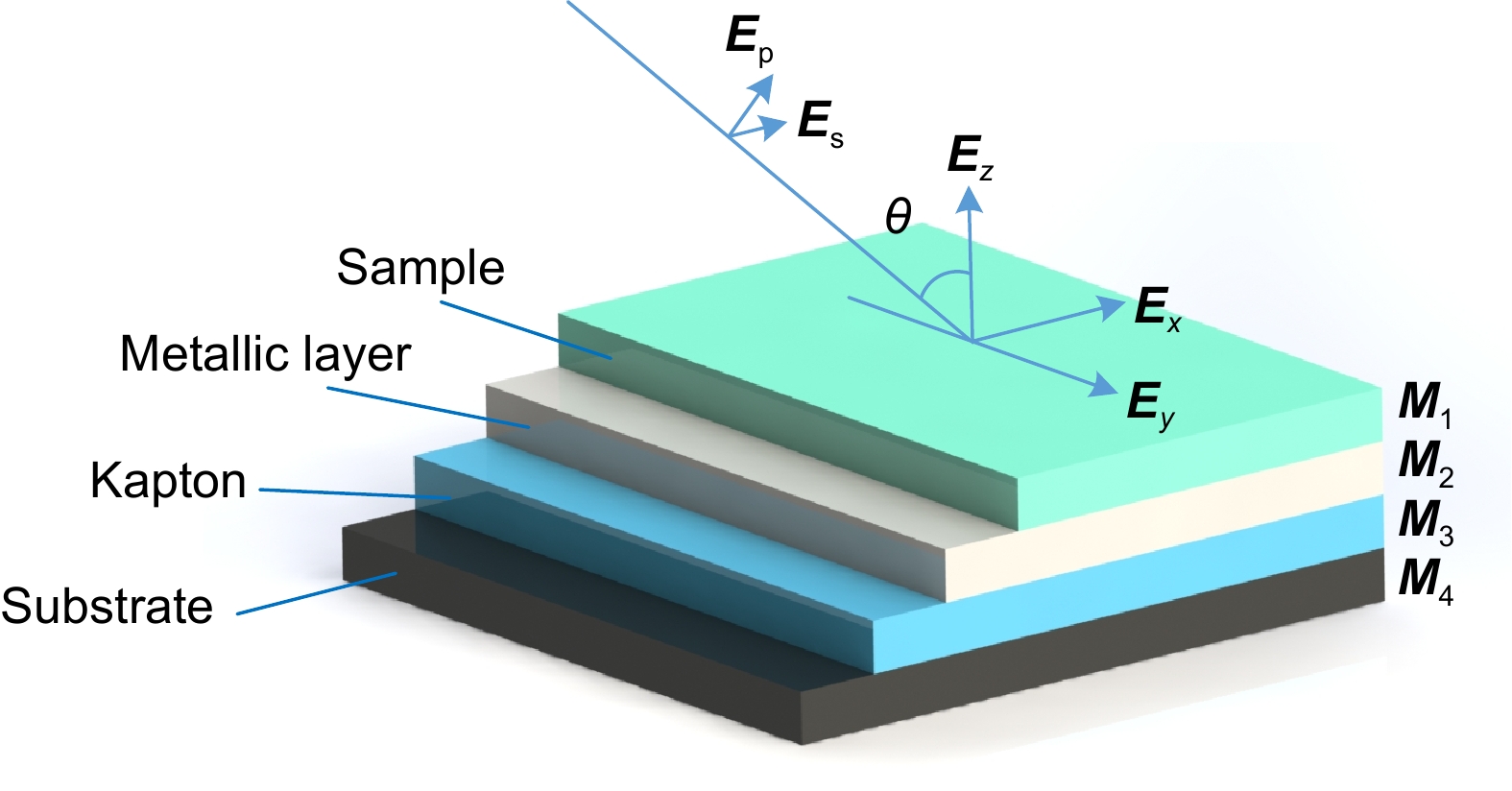
Overview: Optical multilayer interference tomography (OMLIT) is an optical image technique that has an ultrathin sample film affixed on a multilayer structure to enhance the image contrast through light interference. This method is used in correlated light and electron microscopy to first image a large field through an optical microscope providing the navigation of the region of interest for later nanometer-resolution electron microscope imaging. Polarization imaging is widely used in biology to improve system resolution. In order to further improve the imaging contrast and positioning accuracy, a theoretical model of multilayer film polarization imaging is proposed by combining polarization illumination and OMLIT.
At first, taking the metal coating of Fe material as an example, the matrix formalism theoretical model is used to calculate the imaging contrast of multilayer film samples under the illumination of polarized light in two orthogonal directions and unpolarized light. The simulation results show that using the polarized light with an electric field oscillating parallel to the incidence plane (p-polarization) exhibits a much higher imaging contrast than the unpolarized light. This phenomenon can be qualitatively explained by the Fresnel function, which describes the difference in reflectivity and refractivity of two orthogonally polarized lights illumination under different angles. The matrix formalism theoretical model can accurately calculate the effects of the thickness of each film layer and the interference of reflected light between multilayer films. Subsequently, the model is used to simulate nine different metal coatings. The results show that, with the slices of biological samples being unchanged, the imaging contrast increases initially and then remains stable. This phenomenon is related to the imaginary part of the metal refractive index. After the thickness of the metal exceeds 50 nm, the light beam is completely absorbed within the metal coating, hence increasing the thickness no longer causes a change in imaging contrast. Among the nine types of coatings, the Ag coating provided the best imaging contrast. With an incidence angle of 62°, the imaging contrast is vastly enhanced by 138 times. Finally, the effects of tape and substrate are simulated, and the results showed that the imaging contrast in the multilayer films remained unchanged regardless of whether tape and substrate are present or not when the metal coating material is Fe. This indicates that the enhancement effect of tape and substrate on the imaging contrast in the polarized OMLIT model is relatively small.
The presented model provides a theoretical basis for polarization illumination OMLIT, pathing a new technical way for the development of the correlated light and electron microscopy technique.
-

-
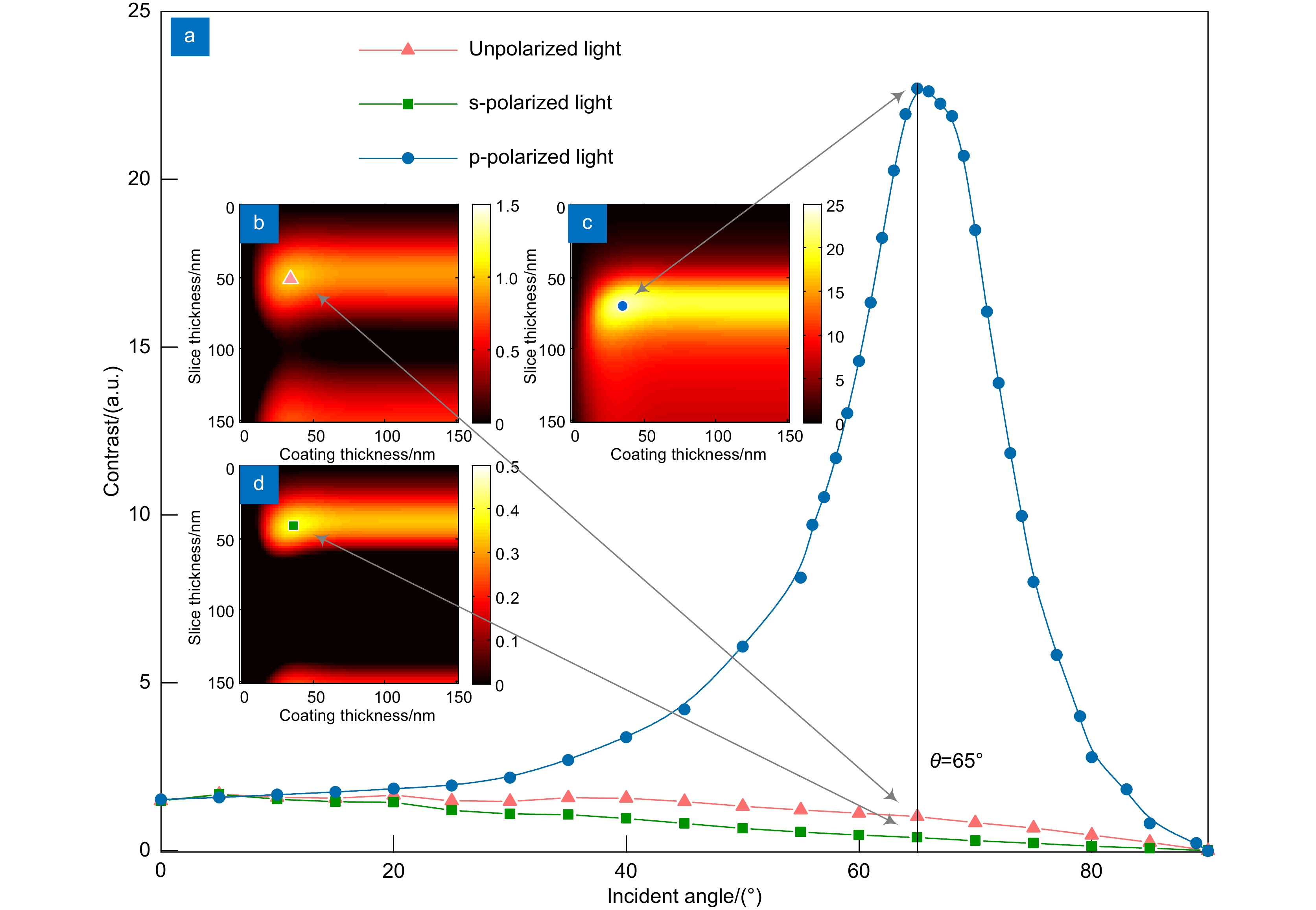
图 2 (a) Fe金属镀层时不同偏振态及角度的影响;65°入射角时(b)非偏振光照明,(c) p偏振照明和(d) s偏振照明时的仿真图像
Figure 2. (a) The effect of different polarization states; Simulation images for (b) unpolarized light, (c) p-polarized light and (d) s-polarized light at 65° incidence angle

图 3 (a) Rp和Rs的菲涅尔方程;(b) Rp和Rs对比度与入射角关系
Figure 3. (a) Fresnel function of Rp and Rs; (b) Contrast of Rp and 和Rs as a function of incidence angle
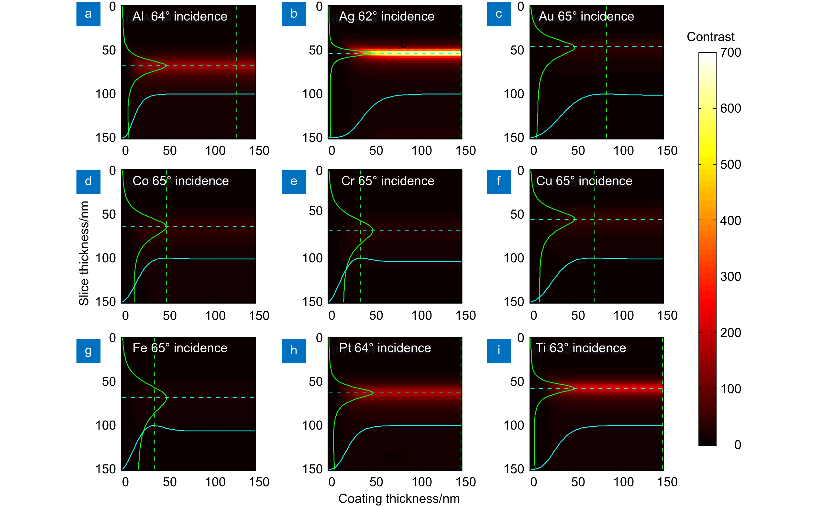
图 4 p偏振照明时不同金属镀层影响。金属镀层为(a) Al,(b) Ag,(c) Au,(d) Co,(e) Cr,(f) Cu,(g) Fe,(h) Pt和(i) Ti时最佳偏振入射角入射下的成像对比度
Figure 4. Effect of different metal coatings with p-polarized lighting. Image contrast of metal coatings with (a) Al, (b) Ag, (c) Au, (d) Co, (e) Cr, (f) Cu, (g) Fe, (h) Pt and (i) Ti at the best polarization incidence angle
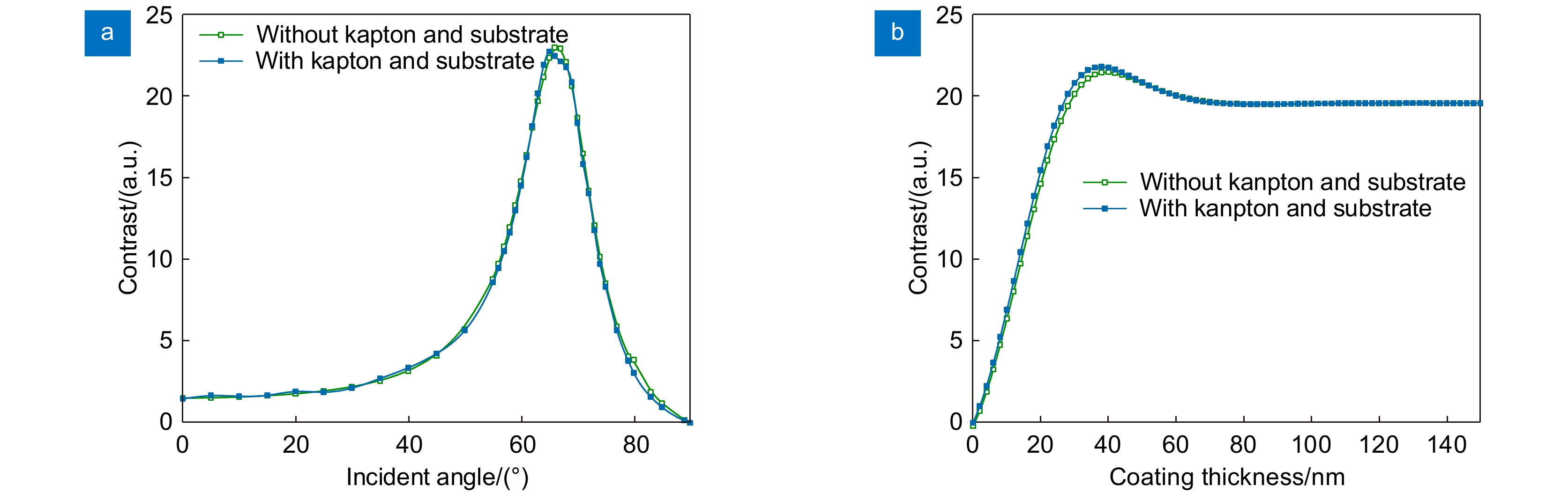
图 5 p偏振照明时卷带与基底作用仿真。(a)不同入射角时Fe最佳成像对比度;(b)不同Fe镀层厚度时成像对比度
Figure 5. Simulation of tape and substrate interaction in p-polarized lighting. (a) The optimal image contrast of Fe at different incidence angles; (b) Imaging contrast at different Fe coating thicknesses
表 1 不同镀层金属下的最佳成像对比度
Table 1. Optimal imaging contrast under different coating metals
Metal Refractive index
at 488 nm[31]Optimum
incidence angle/°Coating
thickness/nmSlice
thickness/nmContrast using
p-polarized lightContrast using
unpolarized lightAl 0.77+5.91i 64 130 68 153.5 3.5 Ag 0.05+3.02i 62 150 54 684.2 4.9 Au 1.13+1.84i 65 86 46 40.5 1.1 Co 1.86+3.51i 65 50 64 44.5 1.6 Cr 2.67+3.28i 65 36 68 28.7 1.2 Cu 1.23+2.54i 65 72 56 48.4 1.5 Fe 2.72+2.86i 65 36 68 22.81 1.0 Pt 0.53+4.28i 64 58 62 175.1 3.4 Ti 0.39+3.50i 63 78 58 226.4 3.7  下载: 导出CSV
-
参考文献
[1] Dance A. Connectomes make the map[J]. Nature, 2015, 526(7571): 147−149. doi: 10.1038/526147a
[2] Brittin C A, Cook S J, Hall D H, et al. A multi-scale brain map derived from whole-brain volumetric reconstructions[J]. Nature, 2021, 591(7848): 105−110. doi: 10.1038/s41586-021-03284-x
[3] De Boer P, Hoogenboom J P, Giepmans B N G. Correlated light and electron microscopy: ultrastructure lights up![J]. Nat Methods, 2015, 12(6): 503−513. doi: 10.1038/nmeth.3400
[4] Fu Z F, Peng D M, Zhang M S, et al. mEosEM withstands osmium staining and Epon embedding for super-resolution CLEM[J]. Nat Methods, 2020, 17(1): 55−58. doi: 10.1038/s41592-019-0613-6
[5] Li A A, Gong H, Zhang B, et al. Micro-optical sectioning tomography to obtain a high-resolution atlas of the mouse brain[J]. Science, 2010, 330(6009): 1404−1408. doi: 10.1126/science.1191776
[6] Gong H, Zeng S Q, Yan C, et al. Continuously tracing brain-wide long-distance axonal projections in mice at a one-micron voxel resolution[J]. NeuroImage, 2013, 74: 87−98. doi: 10.1016/j.neuroimage.2013.02.005
[7] 徐帅, 朱启兵, 黄敏. 手持式食品残留物荧光成像检测系统开发[J]. 激光技术, 2022. https://kns.cnki.net/kcms/detail//51.1125.tn.20221212.1219.001.html
Xu S, Zhu Q B, Huang M. Development of a handheld fluorescence imaging system for detecting food residues[J]. Laser Technol, 2022. https://kns.cnki.net/kcms/detail//51.1125.tn.20221212.1219.001.html.
[8] Giepmans B N G, Deerinck T J, Smarr B L, et al. Correlated light and electron microscopic imaging of multiple endogenous proteins using Quantum dots[J]. Nat Methods, 2005, 2(10): 743−749. doi: 10.1038/nmeth791
[9] Kukulski W, Schorb M, Welsch S, et al. Correlated fluorescence and 3D electron microscopy with high sensitivity and spatial precision[J]. J Cell Biol, 2011, 192(1): 111−119. doi: 10.1083/jcb.201009037
[10] Yao J J, Wang L D, Yang J M, et al. High-speed label-free functional photoacoustic microscopy of mouse brain in action[J]. Nat Methods, 2015, 12(5): 407−410. doi: 10.1038/nmeth.3336
[11] Li X F, Kang L, Zhang Y, et al. High-speed label-free ultraviolet photoacoustic microscopy for histology-like imaging of unprocessed biological tissues[J]. Opt Lett, 2020, 45(19): 5401−5404. doi: 10.1364/OL.401643
[12] Kut C, Chaichana K L, Xi J F, et al. Detection of human brain cancer infiltration ex vivo and in vivo using quantitative optical coherence tomography[J]. Sci Trans Med, 2015, 7(292): 292ra100. doi: 10.1126/scitranslmed.3010611
[13] 李云耀, 樊金宇, 蒋天亮, 等. 光学相干层析技术在眼科手术导航方面的研究进展[J]. 光电工程, 2023, 50(1): 220027. doi: 10.12086/oee.2023.220027
Li Y Y, Fan J Y, Jiang T L, et al. Review of the development of optical coherence tomography imaging navigation technology in ophthalmic surgery[J]. Opto-Electron Eng, 2023, 50(1): 220027. doi: 10.12086/oee.2023.220027
[14] 姜盼秋, 汪平河. 谱域光学相干层析系统的色散补偿技术研究[J]. 光电工程, 2021, 48(10): 210184. doi: 10.12086/oee.2021.210184
Jiang P Q, Wang P H. Research on dispersion compensation technology for SD-OCT system[J]. Opto-Electron Eng, 2021, 48(10): 210184. doi: 10.12086/oee.2021.210184
[15] Schalek R, Kasthuri N, Hayworth K, et al. Development of high-throughput, high-resolution 3D reconstruction of large-volume biological tissue using automated tape collection ultramicrotomy and scanning electron microscopy[J]. Microsc Microanal, 2011, 17(S2): 966−967. doi: 10.1017/S1431927611005708
[16] Fan H, Luo D S, Zhu J L, et al. Optical multilayer interference tomography compatible with tape-based serial SEM for mesoscale neuroanatomy[J]. ACS Photonics, 2021, 9(1): 25−33. doi: 10.1021/acsphotonics.1c00892
[17] Sato S, Ando S. Interferometric imaging ellipsometry: fundamental study[J]. Proc SPIE, 2009, 7405: 74050F. doi: 10.1117/12.825198
[18] Stine K J. Brewster angle microscopy[M]//Steed J W, Gale P A. Supramolecular Chemistry: From Molecules to Nanomaterials. Chichester: John Wiley & Sons, Ltd, 2012.
[19] Ivanova S, Tonchev V, Yokoi N, et al. Surface properties of squalene/meibum films and NMR confirmation of squalene in tears[J]. Int J Mol Sci, 2015, 16(9): 21813−21831. doi: 10.3390/ijms160921813
[20] Pascoe K J. Reflectivity and transmissivity through layered, lossy media: a user-friendly approach[R]. 2001.
[21] Born M, Wolf E. Principles of Optics: Electromagnetic Theory of Propagation, Interference and Diffraction of Light[M]. 6th ed. New York: Pergamon Press, 1980.
[22] Hayworth K J, Morgan J L, Schalek R, et al. Imaging ATUM ultrathin section libraries with WaferMapper: a multi-scale approach to EM reconstruction of neural circuits[J]. Front Neural Circuits, 2014, 8: 68. doi: 10.3389/fncir.2014.00068
[23] Khan R, Gul B, Khan S, et al. Refractive index of biological tissues: Review, measurement techniques, and applications[J]. Photodiagnosis Photodyn Ther, 2021, 33: 102192. doi: 10.1016/j.pdpdt.2021.102192
[24] Nogi M, Handa K, Nakagaito A N, et al. Optically transparent bionanofiber composites with low sensitivity to refractive index of the polymer matrix[J]. Appl Phys Lett, 2005, 87(24): 243110. doi: 10.1063/1.2146056
[25] Lü C L, Cui Z C, Wang Y X, et al. Studies on syntheses and properties of episulfide‐type optical resins with high refractive index[J]. J Appl Polym Sci, 2003, 89(9): 2426−2430. doi: 10.1002/app.12459
[26] Binding J, Arous J B, Léger J F, et al. Brain refractive index measured in vivo with high-NA defocus-corrected full-field OCT and consequences for two-photon microscopy[J]. Opt Express, 2011, 19(6): 4833−4847. doi: 10.1364/OE.19.004833
[27] Sousa A A, Hohmann-Marriott M, Aronova M A, et al. Determination of quantitative distributions of heavy-metal stain in biological specimens by annular dark-field STEM[J]. J Struct Biol, 2008, 162(1): 14−28. doi: 10.1016/j.jsb.2008.01.007
[28] Hua Y F, Laserstein P, Helmstaedter M. Large-volume en-bloc staining for electron microscopy-based connectomics[J]. Nat Commun, 2015, 6(1): 7923. doi: 10.1038/ncomms8923
[29] Beuthan J, Minet O, Helfmann J, et al. The spatial variation of the refractive index in biological cells[J]. Phys Med Biol, 1996, 41(3): 369−382. doi: 10.1088/0031-9155/41/3/002
[30] Deng Z C, Wang J, Ye Q, et al. Determination of continuous complex refractive index dispersion of biotissue based on internal reflection[J]. J Biomed Opt, 2016, 21(1): 015003. doi: 10.1117/1.JBO.21.1.015003
[31] RefractiveIndex. INFO[EB/OL]. https://refractiveindex.info/.
[32] Manion M. Encyclopedia of Optical Engineering[M]. Chicago: American Library Association, 2004.
[33] Kuang C F, Ma Y, Zhou R J, et al. Digital micromirror device-based laser-illumination Fourier ptychographic microscopy[J]. Opt Express, 2015, 23(21): 26999−27010. doi: 10.1364/OE.23.026999
[34] Goodman J W. Speckle Phenomena in Optics: Theory and Applications[M]. Englewood: Roberts & Company, 2007.
-
访问统计
 点击扫一扫
点击扫一扫

图(6)
表(1)
计量
- 文章访问数:
- PDF下载数:
- 施引文献: 0


