
 E-mail Alert
 RSS
RSS
Research on the measurement method of artificial knee joint based on normal vector tracking
-
摘要
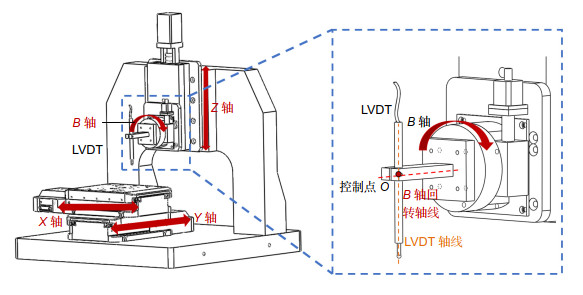
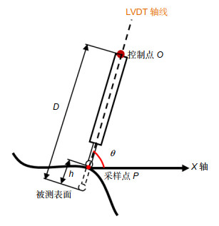
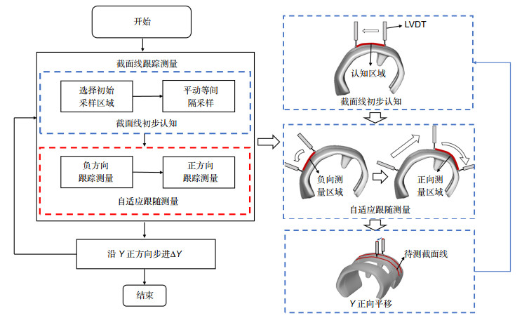
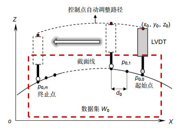
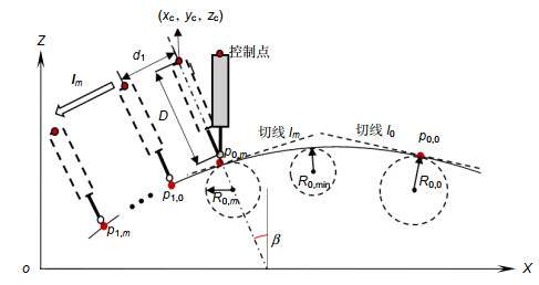
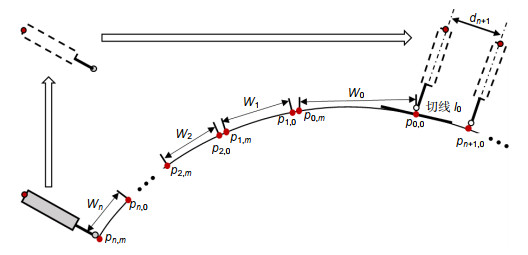
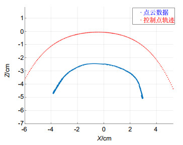
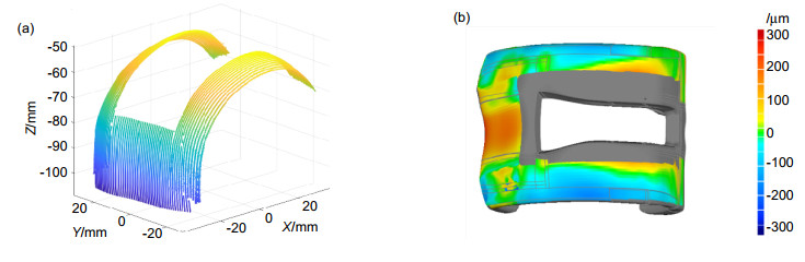
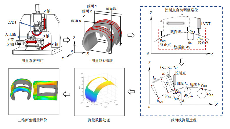
人工膝关节在改善患者关节病情方面有重要的作用,人工膝关节面型偏差会直接影响患者的治疗效果,因此在投入使用之前需要对人工膝关节面型进行高精度评价。人工膝关节面型复杂倾角变化大,并且不同患者的膝关节面型有较大差异,人工膝关节的复杂性和未知性导致其面型的高精度测量较为困难。对此,本文重点提出了一种基于接触式电感直线位移传感器(LVDT)的法矢跟踪测量方法,并搭建了回转扫描测量系统。该方法对已测点进行曲线拟合,预测待测面型的变化趋势,自适应调整LVDT的采样位姿使其近似沿着采样点法矢方向进行测量,实现对大斜率复杂未知曲面的自适应回转测量。通过对标准球的测量实验,标定系统的测量误差为48.21 μm左右;并对人工膝关节模型件进行了测量实验,验证了该方法的可行性。

Abstract
Artificial knee joint plays an important role in improving the joint condition of patients. The surface deviation of artificial knee joint will directly affect the treatment effect of patients. Therefore, it is necessary to evaluate the surface of artificial knee joint with high precision before it is put into use. The slope of the artificial knee joint is complex and varies greatly, and there are great differences in the knee joint surface among different patients. The complexity and unknowability of artificial knee joint make it difficult to measure its surface with high precision. In this paper, a normal vector tracking measurement method based on contact inductance linear displacement sensor (LVDT) is proposed, and a rotary scanning measurement system is built. This method performs curve fitting on the measured points, predicts the changing trend of the measured surface, and adaptively adjusts the sampling position and posture of the LVDT to make it measure approximately along the normal direction of the sampling point, so as to realize the adaptive rotation measurement of the complex and unknown surface with large slope. Through the measurement experiment of the standard ball, the measurement error of the calibration system is about 48.21 μm. In addition, the measurement experiment of the artificial knee joint model is carried out to verify the feasibility of the method.
-
Key words:
- artificial knee joint /
- normal vector tracking /
- rotation measurement /
- unknown surface
-
Overview

Overview: The global demand for total knee arthroplasty for arthropathy patients is increasing year by year. Total knee arthroplasty is the use of artificial knee joint to replace the diseased knee joint to improve the condition. The artificial knee joint is made of biomaterials such as titanium alloy and zirconia ceramics according to the shape of the patient's own joint, and the facial shape will directly affect the therapeutic effect of the patient. Therefore, it is necessary to evaluate the surface shape of artificial knee joint with high precision in production and application. The artificial knee joint is composed of two irregular fan annulus and connecting parts. The curvature change is more than 120° in the sagittal plane and about 16° in the coronal plane. In addition, there are great differences in knee joint shape among different patients, as a result, there is no unified mathematical model. The complexity and unknown nature of the artificial knee joint lead to the lack of an effective high-precision measurement method after processing, and the manufacturing quality of the artificial knee joint cannot be evaluated correctly, which limits the development of the artificial knee joint manufacturing. In order to solve the problem in the surface contour measurement of artificial knee joint, a normal vector tracking measurement method based on contact inductance linear displacement sensor (LVDT) is proposed in this paper, and a rotary scanning measurement system was built. In this method, the curve fitting of the measured points is used to predict the changing trend of the measured surface, and the sampling position and sampling interval of LVDT are adaptively adjusted to make it measure approximately along the normal direction of the sampling points, so as to realize the rotary measurement of the complex and unknown surface with large slope. Through the measurement experiment of the standard ball, the measurement error of the calibration system is about 48.21 μm, and the surface of the artificial knee joint model is measured and evaluated to verify the feasibility of the method.
-

-
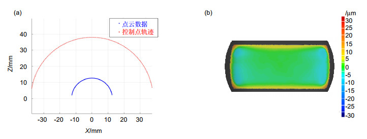
表 1 标准球参数表
Table 1. The parameter table of the standard ball
参数 数值 半径/mm 12.703 PV/μm 0.354 RMS/μm 0.050 球度/μm 0.029  下载: 导出CSV
表 2 标准球测量结果表
Table 2. Measuring result of standard ball measuring results of standard ball
实验序号 RMSE/μm 1 48.95 2 47.37 3 49.23 4 48.68 5 46.83 平均值 48.21
下载: 导出CSV
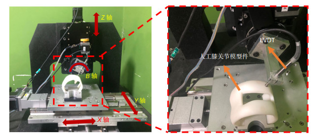
表 3 人工膝关节测量参数表
Table 3. Measurement parameter table of artificial knee joint
参数 数值 数据集中采样点个数 100 初始采样步长d0/μm 50 最大采样步长dmax/μm 150 控制点到LVDT末端距离D/mm 21.5 截面线线间距△y/μm 500 采样步长调整阈值q 3
下载: 导出CSV
-
参考文献
[1] 马涛, 郝林杰, 张育民, 等. 人工膝关节置换术发展现状[J]. 中国现代医生, 2018, 56(36): 160-164.
Ma T, Hao L J, Zhang Y M, et al. Development status of artificial knee arthroplasty[J]. China Mod Doct, 2018, 56(36): 160-164.
[2] Lin Y P, Wang C T, Dai K R. Reverse engineering in CAD model reconstruction of customized artificial joint[J]. Med Eng Phys, 2005, 27(2): 189-193. doi: 10.1016/j.medengphy.2004.09.006
[3] Lustig S, Fleury C, Goy D, et al. The accuracy of acquisition of an imageless computer-assisted system and its implication for knee arthroplasty[J]. Knee, 2011, 18(1): 15-20. doi: 10.1016/j.knee.2009.12.010
[4] 李新宇. 一种新型人工膝关节置换假体的设计及力学评估[D]. 太原: 太原理工大学, 2017.
Li X Y. A new design of total knee replacements and the mechanical evaluation on prostheses[D]. Taiyuan: Taiyuan University of Technology, 2017.
[5] Tuke M, Taylor A, Roques A, et al. 3D linear and volumetric wear measurement on artificial hip joints-Validation of a new methodology[J]. Precis Eng, 2010, 34(4): 777-783. doi: 10.1016/j.precisioneng.2010.06.001
[6] Kudo R, Kitayama T, Tokuta Y, et al. High-accuracy three-dimensional aspheric mirror measurement with nanoprofiler based on normal vector tracing method[J]. Opt Lasers Eng, 2017, 98: 159-162. doi: 10.1016/j.optlaseng.2017.06.024
[7] Binkele T, Hilbig D, Essameldin M, et al. Precise measurement of known and unknown freeform surfaces using Experimental Ray Tracing[J]. Proc SPIE, 2019, 11056: 110561N. doi: 10.1117/12.2526025
[8] 卢科青, 王文, 陈子辰. 未知自由曲面数字化自适应采样方法[J]. 机械工程学报, 2010, 46(9): 143-149. doi: 10.3901/JME.2010.09.143
Lu K Q, Wang W, Chen Z C. Adaptive sampling of digitizing for the unknown free-form surface based on front path detecting[J]. J Mech Eng, 2010, 46(9): 143-149. doi: 10.3901/JME.2010.09.143
[9] Lu K Q, Wang W. A multi-sensor approach for rapid and precise digitization of free-form surface in reverse engineering[J]. Int J Adv Manuf Technol, 2015, 79(9-12): 1983-1994. doi: 10.1007/s00170-015-6960-2
[10] Son S, Park H, Lee K H. Automated laser scanning system for reverse engineering and inspection[J]. Int J Mach Tools Manuf, 2002, 42(8): 889-897. doi: 10.1016/S0890-6955(02)00030-5
[11] Zhang W B, Li J X, Zhang Z. Performance evaluation approach for image mosaicing algorithm[C]//Proceedings of the 25th Chinese Control and Decision Conference, 2013: 3787-3792.
[12] Chun B S, Kim K, Gweon D. Three-dimensional surface profile measurement using a beam scanning chromatic confocal microscope[J]. Rev Sci Instrum, 2009, 80(7): 073706. doi: 10.1063/1.3184023
[13] Wang Y M, Li Z X, Fu Z, et al. Radial scan form measurement for freeform surfaces with a large curvature using stylus profilometry[J]. Meas Sci Technol, 2019, 30(4): 045010. doi: 10.1088/1361-6501/ab052f
[14] Chen S Y, Xue S, Zhai D D, et al. Measurement of freeform optical surfaces: trade‐off between accuracy and dynamic range[J]. Laser Photonics Rev, 2020, 14(5): 1900365. doi: 10.1002/lpor.201900365
[15] Smith K B, Zheng Y F. Multi-laser displacement sensor used in accurate digitizing technique[J]. J Eng Ind, 1994, 116(4): 482-490. doi: 10.1115/1.2902132
[16] Liu H B, Wang Y Q, Huang X P, et al. Isoplanar-based adaptive sampling for model-unknown sculptured surface coordinate metrology using non-contact probe[J]. Int J Adv Manuf Technol, 2013, 64(9-12): 1695-1707. doi: 10.1007/s00170-012-4133-0
[17] Duan Y T, Vo Q, Zhang X D, et al. Novel method of measuring optical freeform surface based on laser focusing probe without calibrating focus error signal[J]. Measurement, 2019, 148: 106961. doi: 10.1016/j.measurement.2019.106961
[18] Maculotti G, Feng X B, Su R, et al. Residual flatness and scale calibration for a point autofocus surface topography measuring instrument[J]. Meas Sci Technol, 2019, 30(7): 075005. doi: 10.1088/1361-6501/ab188f
[19] Bayard D S. High-order multivariable transfer function curve fitting: algorithms, sparse matrix methods and experimental results[J]. Automatica, 1994, 30(9): 1439-1444. doi: 10.1016/0005-1098(94)90009-4
[20] 蔺小军, 王增强, 单晨伟. 自由曲面CMM测量测头半径补偿方法[J]. 航空制造技术, 2011(10): 75-77, 85. doi: 10.3969/j.issn.1671-833X.2011.10.014
Lin X J, Wang Z Q, Shan C W. Method of probe radius compensation for free surface measurement by CMM[J]. Aeronaut Manuf Technol, 2011(10): 75-77, 85. doi: 10.3969/j.issn.1671-833X.2011.10.014
[21] 朱广堂, 叶珉吕. 基于曲率特征的点云去噪及定量评价方法研究[J]. 测绘通报, 2019(6): 105-108.
Zhu G T, Ye M L. Research on the method of point cloud denoising based on curvature characteristics and quantitative evaluation[J]. Bull Survcy Mapp, 2019(6): 105-108.
-
访问统计

 点击扫一扫
点击扫一扫
图(12)
表(3)
计量
- 文章访问数:
- PDF下载数:
- 施引文献: 0


