
 E-mail Alert
 RSS
RSS
-
摘要
针对工作台运动误差,提出了一种基于计算全息的无衍射光莫尔条纹三自由度测量方法。通过液晶空间光调制器(SLM)生成无衍射光,利用两束无衍射光干涉生成莫尔条纹。设计了无衍射光莫尔条纹三自由度测量光路,建立了三自由度运动误差数学模型,并用几何分析法将三种运动误差(偏摆角、滚转角和俯仰角)进行分离。利用旋转台模拟不同大小的三自由度运动误差,带有误差信息的无衍射光和莫尔条纹图案分别由CCD1和CCD2接收。实验结果表明,通过光斑中心偏移量计算出的实际运动误差值接近理论值,测量误差不超过0.0104°,验证了无衍射光莫尔条纹三自由度测量系统的可行性与正确性。

Abstract
Aiming at the motion errors of the linear stage, a measurement method for the determination of three-degree-of-freedom (3-DOF) error motions is proposed based on non-diffracting Moiré fringes produced by computer-generated holograms (CGHs). A liquid crystal spatial light modulator (SLM) is used to generate non-diffracting beams, and two non-diffracting beams form Moiré fringes. A 3-DOF measuring optical path of non-diffracting Moiré fringes is designed. Meanwhile, a 3-DOF mathematical model of motion errors is established, and three kinds of motion errors (yaw angle, roll angle and pitch angle) are separated by geometric analysis method. A rotary table is used to simulate the 3-DOF motion errors on different conditions. The NDB and non-diffracting Moiré fringe patterns are obtained by CCD1 and CCD2 respectively. Experimental results show that the motion errors calculated by the positions of the central points agree well with the theoretical value with the error less than 0.0104°, which can verify the feasibility and correctness of the 3-DOF measurement system for non-diffracting Moiré fringes.
-
Key words:
- 3-DOF measurement /
- non-diffracting beam /
- Moiré fringes /
- SLM
-
Overview

Overview: Error motions of a linear stage directly influence the performance of the precision positioning system in which the stage is used. Therefore, it is a critical task to measure the error motions. A measurement method for the determination of three-degree-of-freedom (3-DOF) error motions based on non-diffracting Moiré fringes is proposed.
A semi-transparent mirror (STM), a beam splitter and a mirror are adopted as the measurement head, which is fixed on the moving stage in order to sense 3-DOF angular errors. Two CCDs are used to capture the non-diffracting beams patterns that are carrying the errors. Computer generated holograms (CGHs) are loaded into a liquid crystal spatial light modulator (SLM) to produce non-diffracting beams. A beam splitter prism (BS1), placed after the SLM, splits the non-diffracting beam into two beams, the transmitted beam and the reflection beam. The reflected non-diffracting beam, after reflection by mirror 2, traveling through BS3, is reflected by the STM, and reaches CCD1. The image of the non-diffracting beams is captured by CCD1. The other beam transmits from BS3 to CCD2 after travelling through STM and BS2. The transmitted non-diffracting beam exiting BS1 passes through an attenuator, and then is reflected by mirror 1, from where it meets the beam from the moving unit. These two non-diffracting beams generate non-diffracting Moiré fringes, which are captured by CCD2.
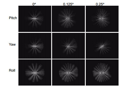
When the stage moves, the position of the central points of the non-diffracting beams (as received by CCD 1) and the forms of Moiré fringes (obtained by CCD 2) will change in relation to different errors. It can measure the 3-DOF errors, which are yaw, pitch, and roll. By analyzing the geometric position of these center points, mathematical models for 3-DOF motion errors are established. Obviously, one of central points in CCD2 will be unchanged while the other one will changes according to different motion errors of stage.
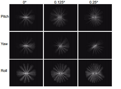
A rotary table is used to simulate the 3-DOF motion errors and demonstrate the theoretical analysis. The measurement head is fixed on the table, which rotates different small angles (0°, 0.125°, 0.25°, 0.375°, 0.5°). The on-diffracting beam and non-diffracting Moiré fringe patterns are obtained by CCD1 and CCD2, respectively. The actual angular displacement is calculated by the offset of the center of the spot with the mathematical models. Compared with the theoretical value, the angular displacement error is less than 0.0104°, which verifies the feasibility and correctness of the 3-DOF measurement system for non-diffracting Moiré fringes.
-

-
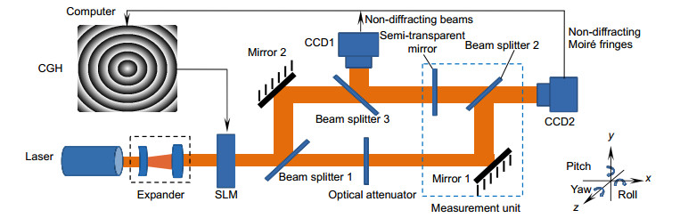
图 2 三自由度运动误差测量系统示意图
Figure 2. Schematic diagram of measurement system of 3-DOF error motions
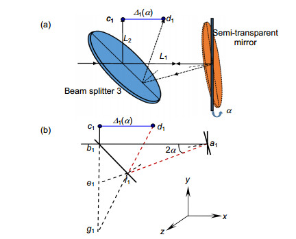
图 3 CCD1中偏摆角误差产生的位移量。
Figure 3. Displacement of the central point generated by the yaw α in CCD1. (a) Schematic diagram; (b) Measuring principle
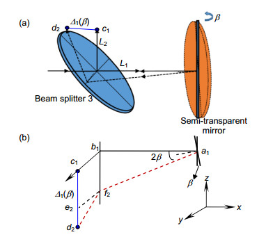
图 4 CCD1中俯仰角误差产生的位移量。
Figure 4. Displacement of the central point generated by the pitch β in CCD1. (a) Schematic diagram; (b) Measuring principle
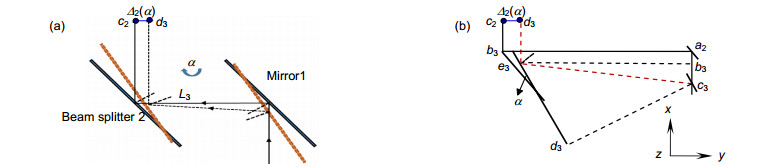
图 5 CCD2中偏摆角误差产生的位移量。(a)示意图;(b)简化原理图
Figure 5. Displacement of the central point generated by the yaw α in CCD2. (a) Schematic diagram; (b) Measuring principle
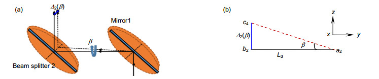
图 6 CCD2中俯仰角误差产生的位移量。(a)模型;(b)原理图
Figure 6. Displacement of the central point generated by the pitch β in CCD2. (a) Schematic diagram; (b) Measuring principle
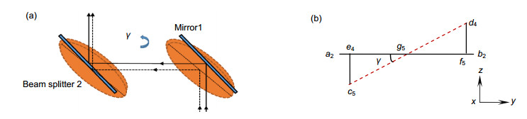
图 7 CCD2中滚转角误差产生的位移量。(a)示意图;(b)简化原理图
Figure 7. Displacement of the central point generated by the roll γ in CCD2. (a) Schematic diagram; (b) Measuring princip
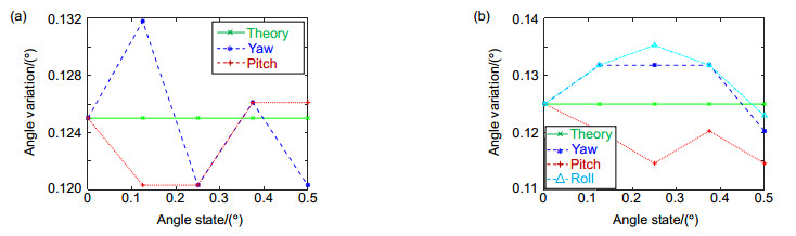
图 10 实验结果。(a) CCD1;(b) CCD2
Figure 10. Experimental results calculated by the images in (a) CCD1 and (b) CCD2
表 1 CCD1、CCD2中三自由度变化对应的光斑中心
Table 1. Central positions of the non-diffracting beams for 3-DOF in CCD1 and CCD2
0° 0.125° 0.25° 0.375° 0.5° CCD1 Yaw α (577, 500) (578, 521) (578, 540) (577, 560) (579, 579) Pitch β (606, 489) (587, 489) (568, 490) (548, 490) (528, 491) Roll γ (561, 551) (560, 551) (560, 550) (561, 550) (560, 551) CCD2 Yaw α (601, 502) (580, 502) (559, 503) (538, 503) (518, 501) Pitch β (600, 530) (599, 550) (598, 569) (599, 589) (602, 608) Roll γ (611, 532) (590, 531) (568, 532) (547, 533) (527, 533)  下载: 导出CSV
表 2 根据CCD1、CCD2中图像运动误差计算结果
Table 2. Motion errors calculated by the images in CCD1 and CCD2
Type of errors Variation error/(°) Pixels moving Pixels increment Calculated values/(°) Measuring error/(°) CCD1 Yaw α 0° 0 0 0° 0° 0.125° 21 21 0.1318° 0.0068° 0.25° 40 19 0.1203° -0.0047° 0.375° 60 20 0.1261° 0.0011° 0.5° 79 19 0.1203° -0.0047° Pitch β 0° 0 0 0° 0° 0.125° 19 19 0.1203° -0.0047° 0.25° 38 19 0.1203° -0.0047° 0.375° 58 20 0.1261° 0.0011° 0.5° 78 20 0.1261° 0.0011° CCD2 Yaw α 0° 0 0 0° 0° 0.125° 21 21 0.1318° 0.0068° 0.25° 42 21 0.1318° 0.0068° 0.375° 63 21 0.1318° 0.0068° 0.5° 83 20 0.1203° -0.0047° Pitch β 0° 0 0 0° 0° 0.125° 20 20 0.1203° -0.0047° 0.25° 39 19 0.1146° -0.0104° 0.375° 59 20 0.1203° -0.0047° 0.5° 78 19 0.1146° -0.0047° Roll γ 0° 0 0 0° 0° 0.125° 21 21 0.1318° 0.0068° 0.25° 43 22 0.1353° 0.0103° 0.375° 64 21 0.1318° 0.0068° 0.5° 84 20 0.1203° -0.0047°
下载: 导出CSV
-
参考文献
[1] Ekinci T O, Mayer J R R, Cloutier G M. Investigation of accuracy of aerostatic guideways[J]. International Journal of Machine Tools and Manufacture, 2009, 49(6): 478-487. doi: 10.1016/j.ijmachtools.2009.01.001
[2] 张昔峰, 黄强先, 袁钰, 等.具有角度修正功能的大行程二维纳米工作台[J].光学 精密工程, 2013, 21(7): 1811-1817. http://d.old.wanfangdata.com.cn/Periodical/gxjmgc201307023
Zhang X F, Huang Q X, Yuan Y, et al. Large stroke 2-DOF nano-positioning stage with angle error correction[J]. Optics and Precision Engineering, 2013, 21(7): 1811-1817. http://d.old.wanfangdata.com.cn/Periodical/gxjmgc201307023
[3] Zhang J H, Menq C H. A linear/angular interferometer capable of measuring large angular motion[J]. Measurement Science and Technology, 1999, 10(12): 1247-1253. doi: 10.1088/0957-0233/10/12/317
[4] Menq C H, Zhang J H, Shi J. Design and development of an interferometer with improved angular tolerance and its application to x-y theta measurement[J]. Review of Scientific Instruments, 2000, 71(12): 4633-4638. doi: 10.1063/1.1326058
[5] 房丰洲, 张奕群, 张国雄.空间物体六自由度定位术[J].航空精密制造技术, 1998(2): 39-41. http://www.wanfangdata.com.cn/details/detail.do?_type=perio&id=QK199800236492
Fang F Z, Zhang Y Q, Zhang G X. A posion-setting method of six-freedoms in space[J]. Aviation Precision Manufacturing Technology, 1998(2): 39-41. http://www.wanfangdata.com.cn/details/detail.do?_type=perio&id=QK199800236492
[6] Kim J A, Bae E W, Kim S H, et al. Design methods for six-degree-of-freedom displacement measurement systems using cooperative targets[J]. Precision Engineering, 2002, 26(1): 99-104. http://d.old.wanfangdata.com.cn/NSTLQK/10.1016-S0141-6359(01)00105-2/
[7] 郑三超, 周素梅, 黄高坤, 等.基于方形孔径微透镜阵列二维叠栅条纹的微小角度测量[J].光学学报, 2018, 38(2): 0205002. http://d.old.wanfangdata.com.cn/Thesis/D01528308
Zheng S C, Zhou S M, Huang G K, et al. Micro-angle measurement based on two-dimensional moire fringes generated by square aperture micro-lens array[J]. Acta Optica Sinica, 2018, 38(2): 0205002. http://d.old.wanfangdata.com.cn/Thesis/D01528308
[8] Khodadad D, Singh A K, Pedrini G, et al. Full-field 3D deformation measurement: comparison between speckle phase and displacement evaluation[J]. Applied Optics, 2016, 55(27): 7735-7743. doi: 10.1364/AO.55.007735
[9] 刘永东, 王佳, 梁晋文.动态目标全姿态激光跟踪测量[J].激光与红外, 1999, 29(3): 148-151. doi: 10.3969/j.issn.1001-5078.1999.03.006
Liu Y D, Wang J, Liang J W. Dynamic target pose measurement by laser tracking[J]. Laser & Infrared, 1999, 29(3): 148-151. doi: 10.3969/j.issn.1001-5078.1999.03.006
[10] 匡萃方, 冯其波, 刘斌.五维信息同时测量的激光方法[J].激光技术, 2005, 29(3): 322-324. doi: 10.3969/j.issn.1001-3806.2005.03.005
Kuang C F, Feng Q B, Liu B. Methods for simultaneously measuring five-dimension information by laser[J]. Laser Technology, 2005, 29(3): 322-324. doi: 10.3969/j.issn.1001-3806.2005.03.005
[11] Wu H, Zhang X M, Gan J Q, et al. High-precision displacement measurement method for three degrees of freedom-compliant mechanisms based on computer micro-vision[J]. Applied Optics, 2016, 55(10): 2594-2600. doi: 10.1364/AO.55.002594
[12] 阮晓东, 李世伦, 诸葛良, 等.用立体视觉测量多自由度机械装置姿态的研究[J].中国机械工程, 2000, 11(5): 571-573. doi: 10.3321/j.issn:1004-132X.2000.05.028
Ruan X D, Li S L, Zhuge L, et al. Study on the pose measurement of multi-degree freedom mechanisms with stereovision[J]. China Mechanical Engineering, 2000, 11(5): 571-573. doi: 10.3321/j.issn:1004-132X.2000.05.028
[13] 吕勇, 冯其波, 刘立双, 等.基于多准直光的六自由度测量方法[J].红外与激光工程, 2014, 43(11): 3597-3602. doi: 10.3969/j.issn.1007-2276.2014.11.016
Lv Y, Feng Q B, Liu L S, et al. Six-degree-of-freedom measurement method based on multiple collimated beams[J]. Infrared and Laser Engineering, 2014, 43(11): 3597-3602. doi: 10.3969/j.issn.1007-2276.2014.11.016
[14] Kroll J J. Six degree of freedom optical sensor for dynamic measurement of linear axes[D]. Charlotte: University of North Carolina at Charlotte, 2003.
[15] Thomas B L, Bass H M, Loftus L K, et al. Laser aligned five-axis position measurement device: 5798828[P]. 1998-08-25.
[16] 赵转萍, 吕晓明, 郑叔芳, 等.运动目标六自由度单束激光跟踪测量方法研究[J].仪器仪表学报, 2001, 22(S2): 35-36, 38. http://d.old.wanfangdata.com.cn/Periodical/yqyb2001z2018
Zhao Z P, Lv X M, Zheng S F, et al. The study of measuring and tracking of six-freedom object using a single laser beam[J]. Chinese Journal of Scientific Instrument, 2001, 22(S2): 35-36, 38. http://d.old.wanfangdata.com.cn/Periodical/yqyb2001z2018
[17] Hsieh H L, Pan S W. Three-degree-of-freedom displacement measurement using grating-based heterodyne interferometry[J]. Applied Optics, 2013, 52(27): 6840-6848. doi: 10.1364/AO.52.006840
[18] Kim J W, Kang C S, Kim J A, et al. A compact system for simultaneous measurement of linear and angular displacements of nano-stages[J]. Optics Express, 2007, 15(24): 15759-15766. doi: 10.1364/OE.15.015759
[19] 别业广, 吕清花, 商逸远, 等.基于无衍射光的三自由度误差测量方法[J].重庆师范大学学报(自然科学版), 2018, 35(4): 81-87. http://www.wanfangdata.com.cn/details/detail.do?_type=perio&id=cqsfxyxb201804015
Bie Y G, Lv Q H, Shang Y Y, et al. A method of three-degree-of-freedom measurement based on non-diffracting beam[J]. Journal of Chongqing Normal University (Natural Science), 2018, 35(4): 81-87. http://www.wanfangdata.com.cn/details/detail.do?_type=perio&id=cqsfxyxb201804015
[20] 翟中生, 赵斌.无衍射光的干涉实验与理论分析[J].光学学报, 2007, 27(8): 1503-1507. doi: 10.3321/j.issn:0253-2239.2007.08.032
Zhai Z S, Zhao B. Experiments and theoretical analyses of non-diffracting beams interference[J]. Acta Optica Sinica, 2007, 27(8): 1503-1507. doi: 10.3321/j.issn:0253-2239.2007.08.032
-
访问统计
 点击扫一扫
点击扫一扫
图(10)
表(2)
计量
- 文章访问数:
- PDF下载数:
- 施引文献: 0


