
 E-mail Alert
 RSS
RSS
-
摘要
针对机车电机整流子维修加工过程中,当前普遍应用的激光调制定位型云母槽削刻系统存在精度较低且需大量人工干预的问题,提出了一种基于机器视觉的云母槽精确定位方法,来克服电机整流子云母槽边缘难以精确提取的难点。本系统首先自主设计了精度补偿算法并构建了定位误差修正模型,基于此搭建了嵌入式系统平台,实现了对云母槽中心线的全自动快速精确定位;准确计算刻刀与中心线的偏差值;精确控制刀头移动到正确的下刻位置。实验结果表明,该仪器能精准计算云母槽中线位置,通过伺服电机对铣刀进行微调对准,并将刻刀定位误差控制在0.02 mm之内,实现了整个操作流程的自动化和精确化。

Abstract
In view of the issue that in the process of locomotive motor commutator maintenance and processing, laser modulation and positioning type mica slot engraving system are widely used in real applications. However, it has low precision and requires a lot of human intervention. To overcome this problem, this paper proposed a precise positioning method of mica slot based on machine vision, which can accurately extract the edge of the motor commutator. The system first independently designs the precision compensation algorithm and constructs the positioning error correction model. Based on this, the embedded system platform is built to realize the automatic, rapid and accurate positioning the center line of the mica slot. Then the system achieves accurate calculation the deviation between the knife and the center line and control the bit tool to move to the correct engraved position. Experimental results indicate that the instrument can accurately calculate the position of the mica slot center line. Through the servo motor control burin to adjustment and aim the midline, the knife positioning error has been controlled between the positive and negative 0.02 mm, achieving the entire operation process automation and precision.
-
Key words:
- machine vision /
- precise positioning /
- precision compensation /
- error correction /
- automation
-
Overview

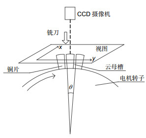
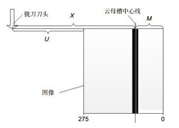
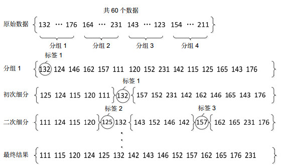
Overview: In the process of using locomotive motor commutator, due to the copper brush constantly rubbing, the copper scraps accumulate in the mica under the action of long time. In this case, the boundary between the copper and the mica slot becomes blurred, thus the motor commutator needs to be repaired on a regular basis. A traditional method is to use a laser-modulated positioning mica slotting system to perform engraving of the mica slot. However, the system detects the location of the mica slot depending on the reflectance of the laser, which is so different between copper bars and mica pieces. It can only get the approximate position of its center line and often appear missing and wrong situation. Therefore, it is necessary to perform error compensation by manual verification before each cutting to avoid unnecessary damage to the motor commutator, and at the same time, this method makes the work efficiency low. In order to improve the positioning accuracy and efficiency, this paper proposes an accurate positioning method of mica trough based on machine vision, which can effectively overcome the difficulties in precise extraction of the mica groove edges belong to motor commutator. In every working cycle, the system utilizes CCD camera to capture the current motor commutator surface image, then transfers the picture to the system’s numerical calculation module. Combing with the positioning error correction model constructed by the system, the self-designed precision compensation algorithm can accurately locate center line of the mica slot. After the positioning result transmitted to the main control unit, the servo system can control the burin to move to the designated position cutting the groove. When the above tasks are completed, the motor commutator can rotate into the next working cycle. The core part of the system is the precision compensation algorithm, which can precisely control each part of the center line positioning process of the mica slot, make precise positioning of the edge of the mica slot and avoid making the scratch mistaken for mica slot. Then finding out the correct location of the center line of the mica slot, the algorithm can also avoid the emergence of some extreme conditions to ensure the stable operation of the entire system. The experimental results show that the system can accurately calculate the midline position of the mica slot and control the positioning error of the knife between positive and negative 0.02 mm, which effectively improves the positioning accuracy and efficiency.
-

-
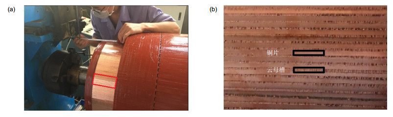
图 1 磨损的电机整流。(a)正在维修的电机整流子; (b)磨损的电机整流子局部细节图
Figure 1. Worn motor commutator. (a) Motor commutator being repaired; (b) Local detail view of worn motor commutator

图 6 边缘检测效果。(a) Sobel算子边缘检测效果图;(b) Laplacian算子边缘检测效果图
Figure 6. Edge detection effect. (a) Edge detection effect diagram of Sobel operator; (b) Edge detection effect diagram of Laplacian operator
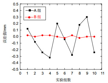
表 1 两种定位系统误差值
Table 1. Error value of two positioning systems
实验序号 A组误差/mm B组误差/mm 1 +0.12 +0.02 2 -0.08 0 3 -0.24 +0.02 4 -0.32 +0.02 5 +0.20 0 6 -0.04 -0.02 7 -0.28 +0.02 8 +0.18 -0.02 9 +0.30 0 10 -0.24 0  下载: 导出CSV
-
参考文献
[1] Fakih B, Dienwiebel M. The structure of tribolayers at the commutator and brush interface: a case study of failed and non-failed DC motors[J]. Tribology International, 2015, 92: 21-28. doi: 10.1016/j.triboint.2015.05.008
[2] Masahiro S, Yomei Y, Hideki C, et al. Rotor repair method and rotor repair apparatus: 2256226A1[P]. 2010-12-01.
[3] Clark S W, Stevens D. induction motor rotor bar damage evaluation with magnetic field analysis[J]. IEEE Transactions on Industry Applications, 2016, 52(2): 1469-1476. doi: 10.1109/TIA.2015.2508424
[4] Fortes M Z, Dos Santos C H R, Oliveira R F, et al. Fast flashover identification methodology on brushed DC machines[J]. Wseas Transactions on Circuits and Systems, 2013, 13: 246-252. https://www.researchgate.net/profile/Marcio_Fortes/publication/267632154_Fast_Flashover_Identification_Methodology_on_Brushed_DC_Machines/links/546090ae0cf295b561620a34.pdf
[5] 何婷婷, 郭建强, 李芳, 等.光电跟踪伺服系统的研究[J].信息技术, 2013(8): 61-63. http://industry.wanfangdata.com.cn/dl/Detail/Thesis?id=Thesis_Y1148167
He T T, Guo J Q, Li F, et al. Photoelectric tracking servo system[J]. Information Technology, 2013(8): 61-63. http://industry.wanfangdata.com.cn/dl/Detail/Thesis?id=Thesis_Y1148167
[6] 刘壮, 李英博, 张浩钧, 等.菲涅尔透镜激光四象限定位系统光学设计[J].光电工程, 2016, 43(9): 62-66, 71. http://www.opticsjournal.net/Articles/Abstract?aid=OJ161209000068Yv2y5A
Liu Z, Li Y B, Zhang H J, et al. Optical design for laser four-quadrant location system based on fresnel lens[J]. Opto-Electronic Engineering, 2016, 43(9): 62-66, 71. http://www.opticsjournal.net/Articles/Abstract?aid=OJ161209000068Yv2y5A
[7] Guan G H, Zhai W Z. Design of a commutator automatic slotting machine based on ccd camera[C]//Proceedings of the 2012 International Conference on Computer Science and Electronics Engineering. Washington, DC, 2012, 3: 689-693.
[8] Isato M, Sawa K, Ueno T. Commutation phenomena and brush wear of dc motor at high speed rotation[J]. IEICE Transactions on Electronics, 2017(9): 716-722.
[9] Zhang J H, Xu Y Y. Design of detection system of traction motor commutator based on computer vision[J]. Advanced Materials Research, 2012, 466-467: 1290-1294. doi: 10.4028/www.scientific.net/AMR.466-467
[10] Litovchenko V V, Kokorin D V, Nazarov D V. A mathematical model of a commutator traction motor[J]. Russian Electrical Engineering, 2014, 85(8): 498-504. doi: 10.3103/S1068371214080082
[11] Weyori B A, Boateng K O, Yeboah P K, et al. Design and implementation of the block matching hybrid median filter for noise removal in color images[J]. International Journal of Innovative Computing Information & Control, 2016, 12(6): 255-263. https://www.researchgate.net/profile/Benjamin_Weyori
[12] Liu A, Zhao Z Y, Zhang C Q, et al. Median filtering forensics in digital images based on frequency-domain features[J]. Multimedia Tools and Applications, 2017, 76(21): 22119-22132. doi: 10.1007/s11042-017-4845-0
[13] Gonzalez R C, Woods R E. Digital Image Processing[M]. 3rd Ed. The USA, Pearson Education, 2011: 347-348.
[14] 朱威, 韩巨峰, 陈朋, 等.基于噪声点多级检测的自适应中值滤波算法[J].光电工程, 2013, 40(10): 63-69. doi: 10.3969/j.issn.1003-501X.2013.10.011
Zhu W, Han J F, Chen P, et al. Adaptive median filter algorithm based on multi-stage noise detection[J]. Opto-Electronic Engineering, 2013, 40(10): 63-69. doi: 10.3969/j.issn.1003-501X.2013.10.011
[15] Aranda L A, Reviriego P, Maestro J A. Error detection technique for a median filter[J]. IEEE Transactions on Nuclear Science, 2017, 64(8): 2219-2226.
-
访问统计
 点击扫一扫
点击扫一扫
图(10)
表(1)
计量
- 文章访问数:
- PDF下载数:
- 施引文献: 0


