
 E-mail Alert
 RSS
RSS
-
摘要
针对传统标定方法对靶标特征点模糊噪声适应性低的问题,提出一种基于彩色编码相移条纹的标定方法。以液晶显示面板为标定靶,依次显示水平和垂直彩色编码相移条纹;通过颜色通道分离,得到正交相移条纹;结合相移理论,以正交相位截断线的交点为特征点;多次改变靶标位姿,提取特征点,结合基于平面二维靶标的标定理论,实现单相机与双目立体视觉系统的标定。此外,在靶标图样四角添加彩色编码相移圆环,实现特征点的自动提取与排序,提高标定效率。实验结果表明,在拍摄靶标图像模糊时,单相机标定的重投影误差为0.15 pixels,标定后双目系统的测量标准偏差为0.1 mm。

Abstract
Aiming at the low adaptability of blurring noise of target feature points in traditional calibration methods, a calibration method based on the color-coded phase-shifted fringe is proposed. Using a liquid crystal display panel as the calibration target, horizontal and vertical color-coded phase-shifted stripes are displayed in sequence; the orthogonal phase-shifted stripes are obtained by separating color channels; based on the phase-shifteg theory, the intersections of the orthogonal phase truncation lines are calculated as the feature points. After changing the target position multiple times and extracting feature points, the plane-based camera calibration technique is applied to realize the calibration of both the single camera and the binocular system. Furthermore, color-coded phase-shift circles are added to four corners of the target pattern to automatically extract and sort feature points. Accordingly, the efficiency of calibration is promoted. The experimental results indicate that when the target image is blurred, the reprojection error of the single-camera calibration is 0.15 pixels, and the standard deviation of the binocular system measurement after calibration is 0.1 mm.
-
Key words:
- camera calibration /
- phase target /
- phase-shift theory /
- 3D measurement
-
Overview

Overview: In the past two decades, camera calibration theory has been continuously developed and improved. The calibration method based on planar two-dimensional targets has been most widely applied. In the actual calibration process, the captured target images would appear to various degrees of blurring due to environmental factors and camera focus errors. The accuracy of feature point extraction would be affected. Since the phase information is not influenced by the blur of the captured image, some scholars have proposed using a liquid crystal display panel that displays phase patterns as a calibration target. The phase code is used to establish the correspondence between feature point world coordinates and image coordinates to achieve high-precision calibration of the camera. Compared with the calibration method based on Fourier analysis, the calibration method based on phase shift theory has higher accuracy. However, its calibration process is cumbersome because multiple images need to be collected for each target pose. Furthermore, such calibration methods require human intervention when extracting feature points, that is, manually selecting four outer corner points to determine a target area for feature point extraction. The calibration process is complicated.
This paper proposes a calibration method based on the color-coded phase-shifted fringe to overcome the shortcomings of the calibration method based on phase-shifted theory. This method encoded a phase-shifted stripe through the RGB channels of a color pattern and used a liquid crystal display panel as a calibration target to sequentially display horizontal and vertical color-coded phase-shifted stripes. Through the color channel separation, orthogonal phase-shifted fringes were obtained. The intersection point of the orthogonal phase truncation line was taken as the characteristic point according to the phase-shifted theory. Applied the calibration theory based on the planar two-dimensional target, the calibration of the single-camera and binocular system was realized by changing the target pose multiple times and extracting feature points. Furthermore, calibration efficiency was improved by adding color-coded phase-shifted rings to the four corners of the target pattern to automatically extract and sort feature points. The single-camera calibration experiment shows that when the target pattern is blurred, the calibration accuracy of the method in this paper is significantly better than that of the chessboard target under the premise that the calibration target pose changes the same number of times. It is slightly higher than the orthogonal sinusoidal fringe target and slightly lower than the orthogonal sinusoidal phase-shifted fringe target. The experiment also shows that the number of pictures collected by this method is only one-third of the orthogonal sinusoidal phase-shifted fringe target. When the total number of collected pictures is the same, the reprojection error of this calibration method is the smallest and the precision is the highest. The calibration accuracy is stable under different defocusing degrees. The binocular system calibration experiment shows that the system has high measurement accuracy after calibration, and it can realize 3D reconstruction of the measured object.
-

-
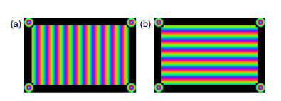
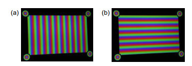
图 1 基于彩色编码相移条纹的相位靶标。(a) 垂直彩色编码相移条纹图;(b) 水平彩色编码相移条纹图
Figure 1. Phase target based on color-coded phase-shift fringe.
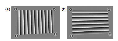
图 3 去除背景后的效果。
Figure 3. The image after removing the background. (a) Vertical wrapped phase; (b) Horizontal wrapped phase diagram

图 4 特征点提取与排序。(a) 特征点提取结果;(b) 定位点排序;(c) 排序后的特征点
Figure 4. Sorting the feature points. (a) Feature point extraction results; (b) Sorting the local points; (c) The feature points after sorting
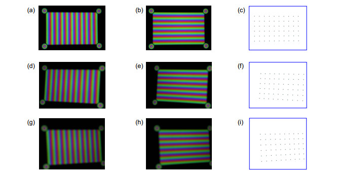
图 6 不同距离下拍摄的靶标以及对应特征点提取结果。
Figure 6. Targets captured at different distances and corresponding feature point extraction results.

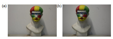
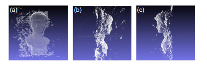
图 8 双目立体视觉系统的左右视目图及棋盘格角点的三维重建。
Figure 8. Left and right image of binocular stereo vision system and 3D reconstruction of chessboard corners. (a) Calibration target taken with the left camera; (b) Calibration target taken with the right camera; (c) 3D reconstruction of chessboard corners
表 3 标定结果
Table 3. Calibration results
Calibration pattern u0/pixels v0/pixels fu/pixels fv/pixels k1 k2 Re-projection error/pixels Chessboard 2741.65 1940.41 15440.2 15451.7 0.54 -0.23 0.47 Ref.[7] method 2769.37 1933.52 15425.3 15435.2 0.34 0.45 0.26 Ref.[9] method 2772.43 1931.73 15455.2 15459.1 0.17 -0.12 0.53 Proposed method 2771.83 1934.47 15382.6 15443.8 0.21 -0.19 0.12  下载: 导出CSV
表 4 标定内参数及重投影误差
Table 4. Calibration parameters and re-projection errors
D/m u0/pixels v0/pixels fu/pixels fv/pixels k1 k2 Re-projection error/pixels 1.4 2735.43 1939.65 15432.6 15398.2 0.66 -3.22 0.19 1.0 2769.52 1961.51 15463.5 15472.8 0.69 -4.32 0.21 0.6 2772.73 1928.32 15443.5 15464.8 0.71 -3.87 0.21
下载: 导出CSV
表 5 双目相机内参数以及重投影误差
Table 5. Parameters of binocular camera and reprojection error
u0/pixel v0/pixel fu/pixel fv/pixel k1 k2 Re-projection error/pixel Left camera 10779.5 10923.3 2821.37 1872.53 0.22 -1.22 0.16 Right camera 10682.4 10521.3 2842.65 1882.22 0.34 1.65 0.16
下载: 导出CSV
表 6 双目系统的结构参量
Table 6. Structural parameters of the binocular system
R T/mm 0.9743 -0.0521 0.2421 -433.1 0.0599 0.9992 -0.0021 -19.06 -0.2310 0.0159 0.9853 6.58
下载: 导出CSV
-
参考文献
[1] Li L L, Zhao W C, Wu F, et al. Experimental analysis and improvement on camera calibration pattern[J]. Opt Eng, 2014, 53(1): 013104. doi: 10.1117/1.OE.53.1.013104
[2] Mallon J, Whelan P F. Which pattern? Biasing aspects of planar calibration patterns and detection methods[J]. Pattern Recognit Lett, 2007, 28(8): 921–930. doi: 10.1016/j.patrec.2006.12.008
[3] Li D, Tian J D. An accurate calibration method for a camera with telecentric lenses[J]. Opt Lasers Eng, 2013, 51(5): 538–541. doi: 10.1016/j.optlaseng.2012.12.008
[4] Liu Z, Wu Q, Chen X, et al. High-accuracy calibration of low-cost camera using image disturbance factor[J]. Opt Express, 2016, 24(21): 24321–24336. doi: 10.1364/OE.24.024321
[5] Bell T, Xu J, Zhang S. Method for out-of-focus camera calibration[J]. Appl Opt, 2016, 55(9): 2346–2352. doi: 10.1364/AO.55.002346
[6] Wang Y W, Chen X C, Tao J Y, et al. Accurate feature detection for out-of-focus camera calibration[J]. Appl Opt, 2016, 55(28): 7964–7971. doi: 10.1364/AO.55.007964
[7] 刘元坤, 苏显渝. 基于傅里叶条纹分析的摄像机标定[J]. 四川大学学报(工程科学版), 2007, 39(6): 149–153. doi: 10.3969/j.issn.1009-3087.2007.06.029
Liu Y K, Su X Y. A new camera calibration technique using FTP method[J]. J Sichuan Univ (Eng Sci Ed), 2007, 39(6): 149–153. doi: 10.3969/j.issn.1009-3087.2007.06.029
[8] 李璐璐, 赵文川, 伍凡, 等. 摄像机标定中的特征点提取算法研究与改进[J]. 光学学报, 2014, 34(5): 0515002. https://www.cnki.com.cn/Article/CJFDTOTAL-GXXB201405028.htm
Li L L, Zhao W C, Wu F, et al. Analysis and improvement of characteristic points extraction algorithms in camera calibration[J]. Acta Opt Sin, 2014, 34(5): 0515002. https://www.cnki.com.cn/Article/CJFDTOTAL-GXXB201405028.htm
[9] Ma M C, Chen X C, Wang K Y. Camera calibration by using fringe patterns and 2D phase-difference pulse detection[J]. Optik, 2014, 125(2): 671–674. doi: 10.1016/j.ijleo.2013.07.055
[10] 杨浩, 蔡宁, 林斌, 等. 基于正弦相位编码的相机离焦标定[J]. 光子学报, 2018, 47(7): 0715002. https://www.cnki.com.cn/Article/CJFDTOTAL-GZXB201807009.htm
Yang H, Cai N, Lin B, et al. Defocus camera calibration based on sinusoidal phase coding[J]. Acta Photon Sin, 2018, 47(7): 0715002. https://www.cnki.com.cn/Article/CJFDTOTAL-GZXB201807009.htm
[11] 葛尉. 基于彩色相位编码条纹投影的三维测量方法研究[D]. 南京: 东南大学, 2016: 4–6.
Ge W. Research on 3D measurement based on color phase-encoded fringe projection[D]. Nanjing: Dongnan University, 2016: 4–6.
[12] Pan J H, Huang P S, Chiang F P. Color phase-shifting technique for three-dimensional shape measurement[J]. Opt Eng, 2006, 45(1): 013602. doi: 10.1117/1.2151160
[13] Heikkila J. Geometric camera calibration using circular control points[J]. IEEE Trans Pattern Anal Mach Intell, 2000, 22(10): 1066–1077. doi: 10.1109/34.879788
[14] 霍炬, 杨卫, 杨明. 基于消隐点几何特性的摄像机自标定方法[J]. 光学学报, 2010, 30(2): 465–472. https://www.cnki.com.cn/Article/CJFDTOTAL-GXXB201002032.htm
Huo J, Yang W, Yang M. A self-calibration technique based on the geometry property of the vanish point[J]. Acta Opt Sin, 2010, 30(2): 465–472. https://www.cnki.com.cn/Article/CJFDTOTAL-GXXB201002032.htm
[15] Zhang Z Y. Flexible camera calibration by viewing a plane from unknown orientations[C]//Proceedings of the Seventh IEEE International Conference on Computer Vision, 1999, 1: 666–673.
[16] Zhang Z H. Review of single-shot 3D shape measurement by phase calculation-based fringe projection techniques[J]. Opt Lasers Eng, 2012, 50(8): 1097–1106. doi: 10.1016/j.optlaseng.2012.01.007
[17] 王娜, 张启灿, 麻珂. 基于彩色编码条纹投影的孤立物体三维测量[J]. 光电子·激光, 2010, 21(8): 1227–1231. https://www.cnki.com.cn/Article/CJFDTOTAL-GDZJ201008030.htm
Wang N, Zhang Q C, Ma K. 3-D shape measurement for isolated objects based on color-encoded fringe projection[J]. J Optoelectron•Laser, 2010, 21(8): 1227–1231. https://www.cnki.com.cn/Article/CJFDTOTAL-GDZJ201008030.htm
[18] 刘大海, 林斌. 利用强度调制消除零频的傅里叶变换轮廓测量[J]. 光子学报, 2011, 40(11): 1697–1701. https://www.cnki.com.cn/Article/CJFDTOTAL-GZXB201111019.htm
Liu D H, Lin B. Fourier transform profilometry using zero frequency elimination based on gray modulation[J]. Acta Photon Sin, 2011, 40(11): 1697–1701. https://www.cnki.com.cn/Article/CJFDTOTAL-GZXB201111019.htm
[19] Huang P S, Zhang S. Fast three-step phase-shifting algorithm[J]. Appl Opt, 2006, 45(21): 5086–5091. doi: 10.1364/AO.45.005086
[20] Lu J, Mo R, Sun H B, et al. Invalid phase values removal method for absolute phase recovery[J]. Appl Opt, 2016, 55(2): 387–394. doi: 10.1364/AO.55.000387
[21] Nellros F, Thurley M J, Jonsson H, et al. Automated measurement of sintering degree in optical microscopy through image analysis of particle joins[J]. Pattern Recognit, 2015, 48(11): 3451–3465. doi: 10.1016/j.patcog.2015.05.012
[22] Chen N Q, Wang J J, Yu L A, et al. Sub-pixel edge detection of led probes based on canny edge detection and iterative curve fitting[C]//2014 International Symposium on Computer, Consumer and Control, 2014, 6: 131–134.
[23] Yuen H K, Princen J, Illingworth J, et al. Comparative study of Hough transform methods for circle finding[J]. Image Vis Comput, 1990, 8(1): 71–77. doi: 10.1016/0262-8856(90)90059-E
[24] Tsai R Y. A versatile camera calibration technique for high-accuracy 3D machine vision metrology using off-the-shelf TV cameras and lenses[J]. IEEE J Robot Autom, 1987, 3(4): 323–344. doi: 10.1109/JRA.1987.1087109
[25] Kaehler A, Bradski G. Learning OpenCV 3: Computer Vision in C++ with the OpenCV Library[M]. Beijing: O'Reilly Media, Inc. , 2016.
[26] 王珊, 徐晓. 基于双目单视面的三维重建[J]. 光学学报, 2017, 37(5): 0515004. https://www.cnki.com.cn/Article/CJFDTOTAL-GXXB201705024.htm
Wang S, Xu X. 3D reconstruction based on horopter[J]. Acta Opt Sin, 2017, 37(5): 0515004. https://www.cnki.com.cn/Article/CJFDTOTAL-GXXB201705024.htm
[27] 孙军华, 杨扬, 张广军. 基于相移的彩色结构光编码三维扫描技术[J]. 光学技术, 2008, 34(1): 122–125. doi: 10.3321/j.issn:1002-1582.2008.01.011
Sun J H, Yang Y, Zhang G J. Three dimensional scanning technique using color structured light patterns based on phase moving coding strategy[J]. Opt Tech, 2008, 34(1): 122–125. doi: 10.3321/j.issn:1002-1582.2008.01.011
-
访问统计


 点击扫一扫
点击扫一扫
图(10)
表(6)
计量
- 文章访问数:
- PDF下载数:
- 施引文献: 0


